Bioretention Systems
Bioretention systems (also known as biofiltration systems or raingardens) promote the filtration of stormwater through a vegetated filter media (NOTE: whilst the user has the option to specify a non-vegetated system, it is strongly recommended that bioretention systems always be vegetated). Non-vegetated systems will generally give poor water quality outcomes and are more likely to clog prematurely. The type and composition of filter medium determines the effectiveness of the pollutant removal, as does the choice of vegetation.
Refer to Modelling Bioretention System Treatment Performance for more details on how bioretention systems are modelled in MUSIC.
In MUSIC, the bioretention node has been further revised, taking advantage of the latest research on biofiltration processes undertaken by FAWB (the Facility for Advancing Water Biofiltration, based at Monash University). Whilst the node has become more ‘complex’, it now allows the user to be much more precise in their specification of the bioretention system that they wish to model. This is important, because research by FAWB has showed that the specifications of a bioretention system - its filter media, its choice of vegetation, the use of a enhancements such as a saturated zone - all play a critical role in determining the treatment performance.
NOTE: It is imperative that the parameters which are specified in the MUSIC model reflect those that have been (or will be) used to construct the system in reality. For example, if the MUSIC model of the bioretention system specifies a TN content of the filter media of less than 1000 mg/kg, then the specification for construction of the system must stipulate this as a requirement for the filter media to be supplied.
Bioretention System Properties
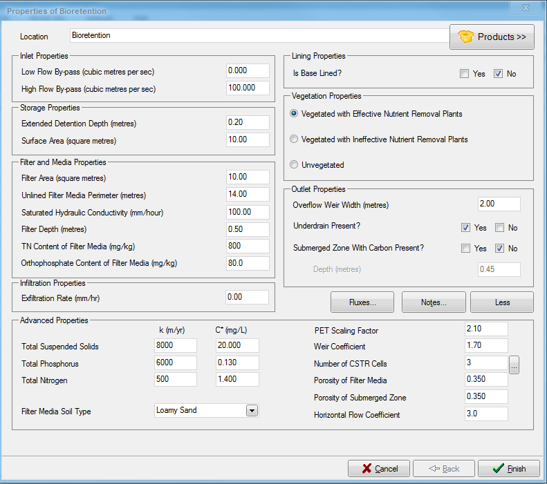
The bioretention system properties dialogue box displays the parameters that describe the key characteristics of the bioretention system. These characteristics are used for the hydrologic routing of stormwater flows through the system, as well as for the prediction of treatment performance. More details on the algorithms used for treatment performance in the bioretention system are provided in Modelling Bioretention System Treatment Performance.
A conceptual diagram of the bioretention system properties in MUSIC is presented below:
Conceptual diagram of bioretention system properties.
Location
The location name will be displayed under the bioretention system node icon on the main worksheet.
Inlet Properties
The inlet properties define the flow rate at which the stormwater begins to bypass the treatment device.
Low Flow Bypass
All of the stormwater that approaches the bioretention system below the user-defined Low Flow Bypass amount (in units of m3/s) will bypass the system. Any flow above the Low Flow Bypass (subject to the presence of a High Flow Bypass) will enter and be treated by the bioretention system.
High Flow Bypass
When the stormwater inflow rate exceeds the user-defined High Flow Bypass amount (in units of m3/s), only a flow rate equal to the High Flow Bypass (less that specified in any Low Flow Bypass) will enter and be treated by the bioretention system. All of the stormwater flow in excess of the High Flow Bypass amount will bypass the bioretetention system and will not be treated. The high flow bypass may be used where inflows to the system are restricted. For example, a diversion pipe into the system may constrain flows.
 Tip Box
The Low and High Flow Bypasses are assumed to occur simultaneously. So for a Low Flow Bypass of 2m3/s, a High Flow Bypass of 8m3/s, and inflow of 10m3/s:
Storage Properties
The Storage Properties define the physical characteristics of the surface storage above the infiltration medium of the bioretention system.
Extended Detention Depth
Defines the maximum depth of water ponding above the filter media before flow starts to discharge over the outflow weir. The Extended Detention Depth is defined as a depth in metres.
Surface Area
Defines the surface area of the bioretention system storage (ie. the surface storage above the infiltration medium) in m2. The hydrologic routing analysis calculates the volume of water in storage during a storm event by multiplying the depth of water in the pond by this surface area. NOTE that where the sides of the extended detention zone are non-vertical, this area will normally be larger than the Filter Area specified in the Filter and Media Properties and should be equivalent to the surface area at half the extended detention depth.
Filter and Media Properties
The filter and media properties define the physical, hydraulic, chemical and biological characteristics of the filtration medium component of the bioretention system. These are all critical for defining the predicted water quality performance of the system; the parameter values chosen should match what will realistically be used for construction of the system. For further guidance, please refer to the guidelines available from FAWB (www.moansh.edu.au/fawb).
Filter Area
Defines the plan area of the filtration medium component of the bioretention system in m2. This can often be less than the surface area of the storage zone (where the extended detention depth has sloped sides).
Unlined Filter Media Perimeter
Defines the perimeter (in metres) of the filter media which is unlined. This parameter is used by MUSIC to calculate the amount of exfiltration that will occur through the sides of the system. Where the entire system perimeter is lined with an impermeable material, the Unlined Filter Media Perimeter should be set to 0.
Example: a rectangular bioretention system with a filtration area measuring 5 m x 2 m is to be constructed. One side (5 m) is to be lined, to avoid potential water migration near adjacent infrastructure. The specified Filter Area is thus 10 m2, whilst the unlined perimeter is 5 + 2 + 2 = 9 m.
Saturated Hydraulic Conductivity
This is the flow water through the filter media at saturation in mm/hr. The FAWB guidelines recommend a range of 100-400mm, but generally, a range of 100-200mm is preferred. Very high flow rates and low soil water retention can result in poor plant growth. It is possible to use lower flow rates although a larger area may be required to compensate. The value chosen should accurately reflect the material to be used, provided in the table below.
| Soil Type | Median particle size (mm) | Saturated Hydraulic Conductivity | |
|---|---|---|---|
| (mm/hr) | (m/s) | ||
| Gravel | 2 | 36000 | 1x10⁻² |
| Coarse sand | 1 | 3600 | 1x10⁻³ |
| Sand | 0.7 | 360 | 1x10⁻⁴ |
| Sandy loam | 0.45 | 180 | 5x10⁻⁵ |
| Sandy clay | 0.01 | 36 | 1x10⁻⁵ |
Filter Depth
Defines the depth of the filter medium in metres. This depth should exclude the drainage layer and transition zone, unless they form part of a Submerged Zone (see Infiltration and Outlet Properties).
TN Content of Filter Media (mg/kg)
Defines the content of nitrogen which is present in the specified filter media (in mg/kg). The FAWB Filter Media Guidelines recommend that the TN content should be kept below 1000 mg/kg for optimal treatment performance. A value of around 750-950 is considered appropriate (a value lower than 600 mg/kg may lead to difficulties in plant establishment within the bioretention system.
NOTE: The value used must match the value which is specified in the contract for supply of filter media for the system in reality.
Proportion of Organic Matter in Filter Media
Defines the organic matter content of the media. Research has shown than an optimal range is between 1 and 3% (lower values will result in difficulties with plant establishment, whilst values higher than 5% will result in leaching of N and P from the media).
NOTE: The value specified must match the value which is specified in the contract for supply of filter media for the system in reality.
Orthophosphate Content of Filter Media
Defines the orthophosphate content of the media, in mg/kg. Research has shown that where the orthophosphate content exceeds 80 mg/kg, there will likely be a leaching of P from the media. A value of less than 55 mg/kg will give optimal treatment performance, provided that the chosen plants are able to establish satisfactorily.
NOTE: The value specified must match the value which is specified in the contract for supply of filter media for the system in reality.
Lining Properties
The lining properties of the base only are specified in this section (details of lining of the walls are specified by specifying the Unlined Filter Media Perimeter in the Filter and Media Properties section.
Is Base Lined
Tick the "Yes” box if the filter is lined with an impermeable liner and the "No” box if it is not. Note that unless an exfiltration rate is entered, no change in performance will result if the base is unlined.
Vegetation Properties
The presence of vegetation in a bioretention system is very important for the nutrient removal performance of a bioretention system, as is the type of plants used. From research undertaken by FAWB, certain species of plants can be far more effective at removing nutrients than others. As such, it is recommended that bioretention systems be planted with plants that have been shown to be effective in nutrient removal, however in certain circumstances, it may be necessary to use plants which may not be optimal. This section allows the user to choose whether effective nutrient removal plants are to be used. Guidance on which plants may be most suitable for bioretention systems should be obtained from organisations with experience in bioretention systems e.g. in Australia, such guidance is provided by FAWB (see www.monash.edu.au/fawb) and in the UK, guidance can be obtained from CIRIA (www.ciria.org).
Outlet Properties
The physical characteristics of the outlet overflow weir are defined in this section of the dialogue box, along with details about how water may infiltrate into surrounding soils and the presence of a submerged (saturated) zone in the bioretention system.
Overflow Weir Width
Defines the width of the overflow weir for the surface storage component of the bioretention system. The overflow weir will only start to carry a discharge of water once the depth in the surface storage reaches the Extended Detention Depth defined above. The Overflow Weir Width is defined as a length in metres. Care needs to be taken to ensure that the weir width used is sufficient to cater for the maximum flow rate expected through the system.
Underdrain present?
Specifies whether there is an underdrain present. When the system is being used as an infiltration system, then ‘No’ should be ticked, but if there is an underdrain that collects the water for discharge to the downstream stormwater system, then ‘Yes’ should be chosen.
Submerged Zone with Carbon Present?
By creating a submerged zone in the base of the bioretention system (ie. by elevating any outlet pipe and using a lined base (may not be necessary in low permeability soils)), the treatment performance will be improved and plant growth and success is likely to be increased. There are specific guidelines on the appropriate depth and composition of the submerged zone. For example, to function optimally, the submerged zone needs an addition of carbon (around 5% by volume), which will help promote denitrification..
NOTE: MUSIC accounts for exfiltration out of a bioretention system only from the base and from any submerged zone depth.
HINT: In the case where the bioretention node is being used to model a vegetated infiltration system, the option of a submerged zone should be specified as being the depth of the filter media, since MUSIC will then take into account the lateral exfiltration through the sides of the system.
Infiltration Properties
Exfiltration rate
Exfiltration from the bioretention system into the underlying soil is modelled by defining the exfiltration rate of these underlying soils (mm/hr). Representative exfiltration rates for different soil types are provided in the table below. The water that seeps from the bioretention system is lost from the catchment, and cannot re-enter the system downstream. Contaminants in the water that is lost to exfiltration are removed from the bioretention system, along with the exfiltrated water and are also lost from the catchment. NOTE that in MUSIC , exfiltration from the ponding zone of the bioretention system is also taken into account.
| Soil Type | Median particle size (mm) | Saturated Hydraulic Conductivity | |
|---|---|---|---|
| (mm/hr) | (m/s) | ||
| Gravel | 2 | 36000 | 1x10⁻² |
| Coarse sand | 1 | 3600 | 1x10⁻³ |
| Sand | 0.7 | 360 | 1x10⁻⁴ |
| Sandy loam | 0.45 | 180 | 5x10⁻⁵ |
| Sandy clay | 0.01 | 36 | 1x10⁻⁵ |
It is possible to record flux data for the bioretention system using Fluxes:
- inflow rate and water quality
- outflow rate and water quality
- low and high flow bypass rate and water quality
- overflow rate and water quality
- total outflow rate (sum of outflow, bypasses and overflow) and water quality
- computed water levels and storage.
Refer to Fluxes for more information about fluxes.

The Notes button allows you to record any important details or assumptions for the bioretention system (for example, you may provide an explanation of how the filter media properties were determined). It is good practice to provide notes of any important assumptions, for future reference by others using the model.
Advanced Bioretention System Properties
The advanced properties section (opened using the ‘More’ button) of the bioretention system properties dialogue box displays the hydraulic characteristics for the overflow weir structure, and the parameters that describe the treatment processes in the bioretention system, including the media soil type, its porosity (along with that of the submerged zone, if present) and the coefficient of horizontal flow (exfiltration through the sides).
k and C* Values
The first order kinetic model adopted in the USTM for the surface storage component of the bioretention system is described by definition of k, the exponential decay rate constant and C*, the background concentration. The rate at which each contaminant is treated, and the background concentration for each contaminant will be different within a bioretention system and different values should be adopted for each contaminant.
Filter Media Soil Type
Defines the type of media which makes up the filter media zone of the bioretention system. Loamy sand, sandy loam and sand are the most commonly used media. The material chosen should match that which will be specified in the construction of the system.
Weir Coefficient
The overflow weir carries a discharge when the water level in the bioretention system pond exceeds the Extended Detention Depth. The overflow weir is modelled as a sharp crested weir whose discharge equation is given by:

where
Q Discharge over the weir
Cw Weir Coefficient
L Overflow weir width
H Height of pond above the Extended Detention Depth.
The default Weir Coefficient of 1.7 may be altered if desired.
The default number of CSTR cells in a bioretention system is three. For more details on CSTR cells, refer to Number of CSTR Cells.
Porosity of Filter Media
Defines the porosity (voids ratio) of the filter media. MUSIC provides a ‘tooltip’ with guidance on the appropriate values to use, depending on the filter media specified. The filter media is normally made up of sand or loamy sand. The following general values are recommended:
Media Type | Typical Porosity |
|---|---|
Loamy sand | 0.35-0.4 |
Sandy loam | 0.35-0.4 |
Sand | 0.3-0.4 |
Gravel | 0.3-0.4 |
Scoria | 0.5-0.6 |
Porosity of Submerged Zone
Defines the porosity (voids ratio) of the submerged zone. MUSIC provides a ‘tooltip’ with guidance on the appropriate values to use, depending on the filter media specified. A submerged zone is normally made up of sand, gravel or scoria. The recommended rules are as shown in the above same (same as the porosity for filter media).
Horizontal Flow Coefficient
MUSIC will simulate exfiltration from the unlined perimeter of the bioretention node whenever there is a submerged zone present (lateral exfiltration will be modelled up to the depth of the submerged zone). Calibration studies have shown that the rate of exfiltration from the wall (sides) of a system will be approximately three times greater than the same area of base (due to the two dimensional infiltration offered by the side). This parameter (of 3) has been specified by default in MUSIC and should only be modified where peer-reviewed published data is available to support such a modification.
Evapotranspiration losses
The method of calculating evapotranspiration from bioretention systems has been enhanced. In the previous version of MUSIC, evapotranspiration was a function of soil moisture and a term, Emax, which is used to describe the maximum daily evapotranspiration rate. The Emax value was derived from experiments using biofilter columns planted with Carex appressa, and was applied as a constant rate. More recently, field experiments on biofilters (see for example Hamel et al. 2011 and 2012) have enabled the MUSIC team to develop a more sophisticated and precise prediction of evapotranspiration, taking into account seasonal variation. We have done this by developing a ratio between potential evapotranspiration (PET) and the measured ET. This scaling factor has then been used to develop a seasonally-adjusted Emax figure on a monthly basis, such that: Emaxj = scaling factor * PETj, where Emaxj is the Emax value for month j, and PETj is the potential evapotranspiration for month j.
The change means that MUSIC will provide more accurate predictions of evapotranspiration and can thus provide more precise information on the impact of biofiltration systems on the water balance and flow regime.
Pollutant Removal through the Filtration Medium
In MUSIC, the pollutant removal performance through the filtration medium is based on the extensive research undertaken on bioretention systems in Australia by the Facility for Advancing Water Biofiltration (FAWB); see www.monash.edu.au/fawb. The treatment performance is governed by a series of functions, which determines outflow concentrations and/or removal rates for TSS, TP and TN .The function takes into account all important characteristics of the bioretention system and its operating conditions, including:
- Choice of vegetation (vegetated with effective nutrient removal species, vegetated with ineffective nutrient removal species, unvegetated);
- Amount of exfiltration (presence of lining, etc);
- Presence of a submerged zone (which helps promote denitrification and also helps to ensure that the media does not dry out during long dry periods, the latter has been shown to result in leaching of nutrients upon rewetting of the media); and
- Presence or absence of an underdrain.
For more information, please refer to the see the section on Modelling Bioretention System Treatment Performance, where a full description is provided.