Infiltration Systems
Infiltration systems allow water to be ‘lost’ from the stormwater conveyance system, by means of infiltration. They are a very important treatment technique, because they can be a very effective method in restoring flow regimes to ‘pre-development’ levels. Pre-treatment is an essential requirement for infiltration systems, to reduce their risk of clogging and to prolong their lifespan.
NOTE: In MUSIC, two types of infiltration systems can be modelled:
- Traditional unvegetated infiltration systems (e.g soakaways, rubble trenches, french drains etc); use the Infiltration node.
- Vegetated infiltration systems: In MUSIC v5, these are now to be modelled using the Bioretention node, selecting appropriate parameters such as no collection pipe and unlined base, because this will take into account the effect of vegetation on both water quality and also water losses due to evapotranspiration.
NOTE: In MUSIC, a number of key changes have been made to the infiltration node, to better reflect the real behaviour of infiltration systems:
- The perimeter of the system is now taken into account, with infiltration through the sides (walls) of the systems modelled
- The porosity of the filter media taken into account, in order for the depth of water to be modelled at each time-step, so that the infiltration area (“wetted perimeter”) can be calculated
- As with other nodes, the user can now specify a storage height-discharge relationship, if required.
MUSIC models the infiltration system by taking into account infiltration through both the base and sides of the system (unlike MUSIC v3 which assumed that infiltration occurred only through the base). It is important to note that there is no option to include lining of the base of the infiltration system. However, you can take into account lined walls, by subtracting them from the specified Infiltration Media Perimeter specified in MUSIC.Treatment in the infiltration system is assumed to occur only in the ponding (extended detention) zone; no treatment is modelled in the infiltration media. Whilst this is not strictly true, it must be remembered that MUSIC ‘loses’ water that is infiltrated and so there is no benefit in modelling the treatment performance further.
Infiltration System Properties
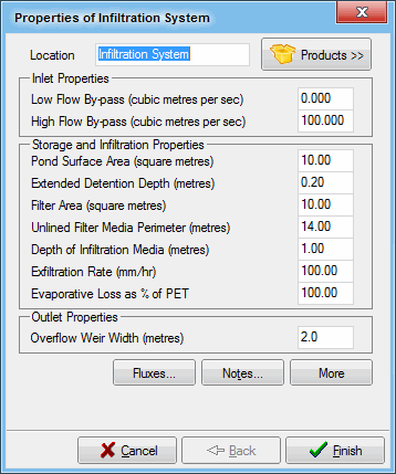
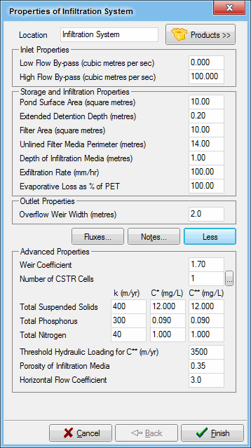
The infiltration system properties dialogue box contains the parameters that describe the basic physical characteristics of the infiltration system. A description of each of the parameters is given below.
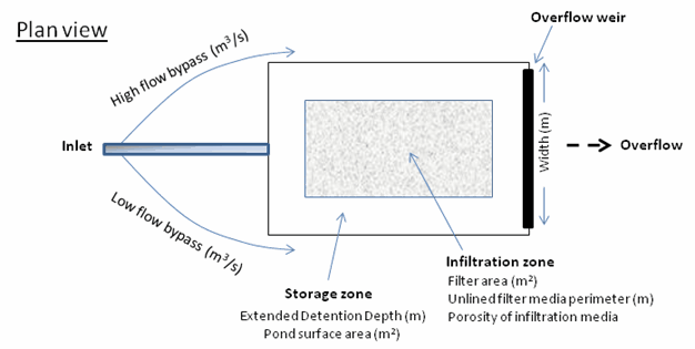
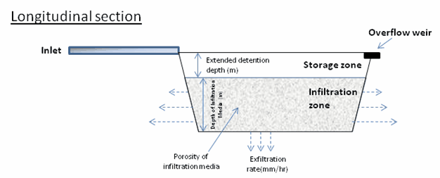
A conceptual diagram of the infiltration system properties in MUSIC is presented below:
Conceptual diagram of infiltration system properties.
Location
The location name will be displayed under the infiltration system node icon on the main worksheet.
Inlet Properties
The Inlet Properties define the physical characteristics of the inlet section of the infiltration system.
Flow is hydrologically routed through the infiltration system, based on the characteristics defined by the user.
Low Flow Bypass
All of the stormwater that approaches the infiltration system below the user-defined Low Flow Bypass amount (in units of m3/s) will bypass the system. Any flow above the Low Flow Bypass (subject to the presence of a High Flow Bypass) will enter and be treated by the infiltration system.
High Flow Bypass
When the stormwater inflow rate exceeds the user-defined High Flow Bypass amount (in units of m3/s), only a flow rate equal to the High Flow Bypass (less that specified in any Low Flow Bypass) will enter and be treated by the infiltration system. All of the stormwater flow in excess of the High Flow Bypass amount will bypass the infiltration system and will not be treated.
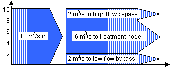
Tip Box
The Low and High Flow Bypasses are assumed to occur simultaneously. So for a Low Flow Bypass of 2m3/s, a High Flow Bypass of 8m3/s, and inflow of 10m3/s:
Storage and Infiltration Properties
The Storage and Infiltration Properties define the physical characteristics of the infiltration system.
Pond Surface Area
Defines the surface area of the infiltration system in m2. The hydrologic routing analysis calculates the volume of water in storage during a storm event by multiplying the depth of water below the overflow weir by this surface area.
Extended Detention Depth (metres)
Defines the maximum depth of water ponding above the infiltration media before flow starts to discharge over the outflow weir. The Extended Detention Depth is defined as a depth in metres.
Filter Area
Defines the surface area of the infiltration media in m2. Where the infiltration system’s extended detention zone has non-vertical sides, the infiltration area (filter area) will normally be smaller than the pond area above it.
Unlined Filter Media Perimeter
Defines the perimeter of the infiltration media, in metres. For example, for a rectangular system, the perimeter would be the 2 • length + width. The perimeter is necessary, because MUSIC takes into account the infiltration that will occur through the sides of the system.
NOTE: MUSIC does not explicitly allow lining to the base or walls of an infiltration system. If you wish to include lining, then you can either (a) take the lined part into account when calculating the Perimeter of the Infiltration Media (ie. subtract the lined component) or (ii) use the Bioretention node, as it allows a complex system with part of the infiltration area lined.
Depth of Infiltration Media
Defines the depth of the infiltration media in metres. The depth is from the base of the infiltration system to the top surface of infiltration media.
Exfiltration rate
Infiltration into the underlying soil is given by the exfiltration rate (mm/hr). Representative exfiltration rates for different soil types are provided in the table below. The water that exfiltrates from the infiltration system is lost to the treatment train, and does not re-enter the system downstream. Contaminants in the water that is lost to infiltration are also removed, along with the infiltrated water and are also lost from the catchment. Representative infiltration rates for different soil types are shown in the following table. NOTE that in MUSIC 4 and above, exfiltration from the ponding zone of the infiltration system is also taken into account.
Soil Type | Median Particle Size (mm) | Saturated Hydraulic Conductivity | |
(mm/hr) | (m/s) | ||
Gravel | 2 | 36000 | 1 x 10⁻² |
Coarse sand | 1 | 3600 | 1 x 10⁻³ |
Sand | 0.7 | 360 | 1 x 10⁻⁴ |
Sandy loam | 0.45 | 180 | 5 x 10⁻⁵ |
Sandy clay | 0.01 | 36 | 1 x 10⁻⁵ |
In theory, the infiltration rate specified in MUSIC should be the rate which limits its performance. In most cases, this will be the infiltration rate of the surrounding soils, although in some cases (e.g. in areas with very sandy soils) the limiting rate could be that of the filter media itself.
Evaporative Loss
Evaporation from the infiltration system basin can be modelled by defining the evaporative loss rate, defined as a percentage of the daily Potential Evapotranspiration data contained in the Meteorological Template used to create the model. The water that evaporates is lost from the catchment. Contaminants in the water that is lost to evaporation remain within the infiltration system, until they are infiltrated, or overflow, whichever occurs first.
Outlet Properties
Overflow Weir Width
Defines the width of the overflow weir for the infiltration system. The Overflow Weir Width is defined as a length in metres.
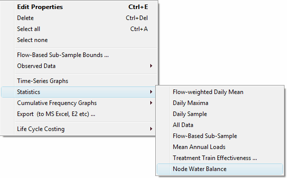
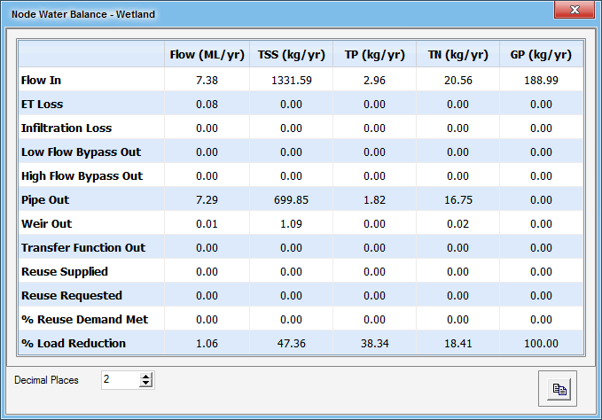
You can use the node water balance report to obtain basic information on the overall water balance at the infiltration system, including basic information on reuse at the node. To do this, select node water balance from the list of available reporting boxes by right clicking on the node.
A reporting window will then be presented showing the water balances for various inflows and outflows at the infiltration system as shown below.
It is possible to record flux data for the infiltration system:
- inflow rate and water quality
- outflow rate and water quality
- low and high flow bypass rate and water quality
- overflow rate and water quality
- total outflow rate (sum of outflow, bypasses and overflow) and water quality
- computed water levels and storage
- water re-use demand and actual volume supplied.
Refer to Fluxes for more information about fluxes.
The Notes button allows you to record any important details or assumptions for the infiltration system (for example, you may provide an explanation of how the volume was calculated, or the infiltration rate was measured). It is good practice to provide notes of any important assumptions, for future reference by others using the model.
Advanced Infiltration System Properties
The advanced properties section (opened using the button) of the infiltration system displays the parameters that describe the hydraulic characteristics for the overflow weir, and the parameters that describe the treatment process in the infiltration system.
Weir Coefficient
The overflow weir carries a discharge when the water level in the infiltration system pond exceeds the Extended Detention Depth. The overflow weir is modelled as a broad crested weir whose discharge equation is given by:
where:
Q Discharge over the weir
Cw Weir Coefficient
L Overflow weir width
H Height of pond above the Extended Detention Depth.
The default Weir Coefficient of 1.7 may be altered if desired.
For details on CSTR cells, refer to Number of CSTR Cells. For infiltration systems:
- k and C** - The rate at which each contaminant is treated, and the background concentration for each contaminant will be different within an infiltration system and different values should be adopted for each contaminant; and
- C** - Normally C** is less than C*. The C** value is of minor importance in an infiltration system, where most, if not all flow, during dry weather conditions, will be ‘lost’ due to infiltration, and not conveyed downstream through the treatment train.
Porosity of Infiltration Media
Defines the porosity (voids ratio) of the infiltration media. The following general values are recommended:
Media Type | Typical Porosity |
|---|---|
Loamy sand | 0.35-0.4 |
Sandy loam | 0.35-0.4 |
Sand | 0.3-0.4 |
Gravel | 0.3-0.4 |
Scoria | 0.5-0.6 |
The porosity affects the performance of the infiltration system by determining the volume of water which is necessary to “fill” the filter media, thus potentially creating an overflow event.
Horizontal Flow Coefficient
MUSIC models the influence of infiltration through the sides of the system. This is important, since a number of studies have shown that this can represent a very high proportion of the total infiltration of the system. MUSIC has been calibrated for a number of infiltration systems, both in the field and using detailed laboratory studies, to derive a default Horizontal Flow Coefficient of 3.0 (ie. the lateral infiltration rate being effectively three times the rate of vertical infiltration through the base). You should only modify this value where they have appropriate data to calibrate it; these data should preferably be based on published, peer reviewed studies.
