Controlled splitter node
A controlled splitter is used to divide water travelling down a single branch into two different branches. Controlled splitters can be used to represent distributaries (a system with multiple end-points), effluents (a split in the river into the main channel and a smaller channel), anabranches (where a smaller section of river branches away from the main channel and then rejoins the main channel further downstream), or losses (where water is leaving the system).
A controlled splitter models the behaviour of both:
- a natural system; and
- a system where the flow down the effluent can be controlled by some kind of regulating structure.
A controlled splitter node does not consider what happens to a flow after splitting. In the case of anabranches, there may be multiple order paths and orders may be subject to optimisation.
Modelling systems
To model a system using the controlled splitter node, use the piecewise linear editor to describe the relative proportions of water that either continue along the main branch or enter the effluent. Values can be entered either manually or imported from a comma-separated value (.CSV) file using the format shown in Table 1.
Table 1. Controlled splitter node (data file format)
| Row | Column (comma-separated) | ||
|---|---|---|---|
| 1 | 2 | 3 | |
| 1 | Upstream flow (ML/d) | Minimum Effluent Flow (ML/d) | Maximum Effluent Flow (ML/d) |
| 2 | 0 | 0 | 0 |
| 3..n | flow | min | max |
For a natural system, set the minimum effluent flow equal to the maximum effluent flow. This ensures that flow down the effluent is purely a function of the upstream flow. For a regulated system, ensure that the relationship-pair delimits the relative proportions of water, depending on whether the regulating structure is fully closed, fully open, or at some point in between.
A controlled splitter node is operated to minimise the increase in orders for the main channel, while ensuring that orders generated for the effluent are still met. Refer to the Source Scientific Reference Guide for details on setting up the node for this. To minimise loss on the main channel, the initial position is that the regulator is considered to be fully closed. Next, the regulator is opened sufficiently to meet the orders on the effluent. Additional orders are then generated (if required) to ensure that there is sufficient upstream flow to meet the combined requirements of the main channel and effluent.
There are three possible ordering scenarios:
- Orders on the main channel will generate sufficient effluent flow to meet orders on the effluent. In this case, no additional orders need to be generated;
- Orders on the effluent are greater than or equal to the minimum effluent flow generated by main channel orders but less than or equal to the maximum effluent flow for the combined main channel and effluent orders. In this case, additional orders need to be generated; or
- Orders on the effluent are greater than the maximum effluent flow for the combined main channel and effluent orders. In this case, the requirements can not be satisfied by adding more water to the system.
Defining splitter behaviour
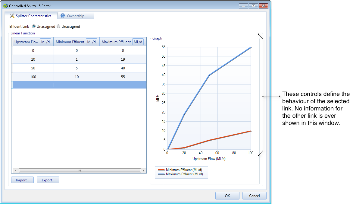
A simple splitter is one that models the behaviour of a natural system, whereas a controlled splitter node models the behaviour of a system where flow down the effluent can be controlled by some kind of regulating structure. You can configure the basic behaviour of a splitter using the Splitter Characteristics tab (Figure 1). To configure the splitter, first ensure that each branch has been linked to a downstream node. Then, define which downstream link represents the effluent. By default, the other link represents the main channel. To do this, refer to the radio buttons near the top of the Splitter Characteristics tab. Then enter a relationship between flow upstream of the node and flow down the effluent. The flow down the main channel is calculated automatically at run time.
Figure 1. Controlled splitter node (Splitter characteristics)
Ownership of unallocated flows from a controlled splitter can be distributed according to owned amounts or by selecting different proportions to the owned amounts. Refer to Controlled splitter .