Supply point node
A Supply Point node (Figure 1) represents a location in the river where water can be extracted to meet demands. You can specify whether water is to be taken from regulated water, unregulated water or groundwater sources.
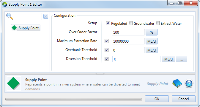
Figure 1. Supply Point node
Source determines the travel time from the closest and further storages to the supply point. This is done using the defined routing models on the links. Note that for storage routing models, you must enter an Average regulated flow (refer to Average regulated flow), which is used to determine the travel time. After running a scenario, the calculated travel time can be viewed in the Recording Manager under type Miscellaneous and attribute Rules-based orders. Refer to Ordering for more information.
If there are multiple upstream storages which can provide water to the supply point then Source automatically determines which storage is used. In a rules based model, this works as follows:
- If the storages are in series then all orders are sent to the closest storage. This storage must be configured so that it orders water from upstream storages to maintain a target operating level; and
- If the storages are in parallel then a confluence node is used to join the two regulated branches. Rules specifying how to distribute orders between the two branches are specified at the Confluence node.
You must set the maximum extraction rate (ML/day) for groundwater sources. You can set a limit for the overbank and diversion thresholds as well. Disable the Extract Water checkbox for demand models which require a flow at the supply point, but require the flow to remain in-stream, ie., the order will not actually be extracted. This could be used for shepherding environmental releases, for example.
The absence of a limit on supply point pumping capacity can lead to a situation where the Maximum Extraction Rate result set cannot be displayed because it will contain infinite values resulting in an empty graph. If this occurs, consider setting both a finite limit on pumping capacity and an overbank threshold.
Setup
This determines where water will be extracted, as follows:
- Enabling Extract water checkbox will ensure that the supply point extracts water. If disabled, water will not be given to the water user, and it will be passed downstream. This is the only difference between enabling and disabling the checkbox;
- The Groundwater checkbox signifies the supply point as a groundwater. The practical difference this makes is that the supply point essentially has unlimited water to draw from; and
- Enabling the Regulated checkbox essentially means that the supply of water to the water user is regulated.
Over Order Factor
This is a percentage factor representing additional water released to meet a particular order, eg a factor of 1.2 or 120% means that the demand is scaled up by 20% in the ordering phase. The additional water is sourced from the upstream storage.
During the flow phase, the extraction actually available to the water user is the minimum of i) the original order (not including the over order factor), or ii) the physical extraction capacity, or iii) any river flow constraints.
The over order factor does not necessarily need to incorporate all estimated delivery losses in the system. If there are upstream nodes or links which simulate losses in the system between the storage and the supply point, Source automatically increases the order to account for estimates of those losses. Refer to the individual node descriptions in the Source Scientific Reference Guide for methods used to estimate losses.
The over order factor is used to add further contingency to a storage release. It should therefore only be calibrated after the physical characteristics of the system have been completely configured. It is up to you to select (or calibrate) an over order factor which is realistic for the system (to ensure that unnecessary water is not released from the storage).
Units: Percentage or proportion
Allowable range: Positive integer (%) greater than or equal to 100. Values of less than 100 (%) or 1 (proportion) are changed back to 100% or 1.
Default value: 100%
Checking constraints
When a constraint is enforced, there may be a difference between the amount of water ordered and released. The differences are recorded in the Recording Manager. For more information, refer to Identifying constraints.
Overbank Threshold
The overbank threshold should be configured if you want to simulate floodplain harvesting by the water user. Overbank flow occurs if the flow rate in the river rises above the specified overbank threshold. Any overbank water can be used to meet the demand model or water user storage requirements without incurring a debit on the water user’s accounts.
Diversion Threshold
The supply point will not be able to pump any water below the diversion threshold. It tries to mimic the fact that the pump may not be at the very bottom of the river. Therefore, you need a certain volume of water in the river before you can pump any at all. It affects the system during the flow phase of the supply point only.