Water user node
- Demand Models – forecasts water demand and provides return flow to account holders (Figure 1). Several types of models are available, including time-series demand, monthly pattern, crop models and environmental demand;
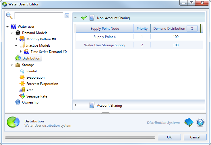
- Distribution – manages orders and extractions through accounts when resource assessment and accounting functions are enabled (Figure 2). A simple distribution system is also available for cases where accounting is not required; and
- Storage – manages water user storages such as on farm storages (OFS). Refer to Figure 3.
When uploading time-series files for any model, note that the data files do not stipulate units. Select the appropriate units in the feature editor using the Units: drop-down menu.
Figure 1. Water User node (model selection)
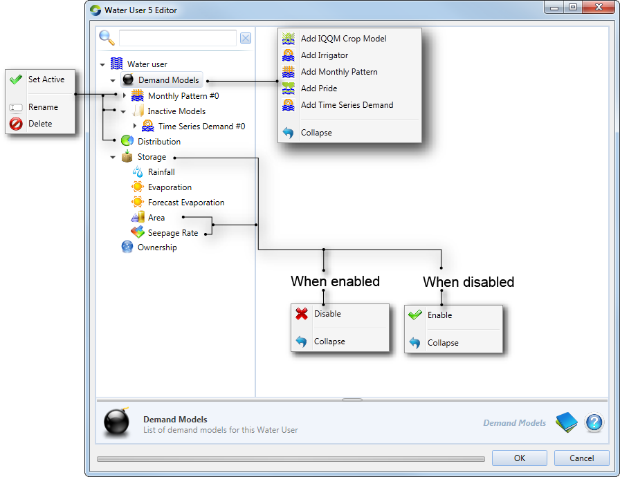
Figure 2. Water User node (Distribution, Non-Account Sharing)
In Source, each water user node must be connected to at least one supply point node, but may be connected to more than one supply point node. Each supply point node to which a water user node is connected can supply water to the water user.
Defining demand models
You can add a demand model to a water user node by right-clicking Demand Models and choosing the appropriate model from the contextual menu, as shown in Figure 1.
When you add a new demand model, it is given a default name which is derived from the type of model. You can rename it by right-clicking the model and choosing Rename from the contextual menu.
You can also add and configure multiple demand models on each water user node, but only one of the models can be active at a time. You can select which one should be the active model by choosing Set Active from the contextual menu.
A model can be deleted by selecting it, then right-clicking and choosing Delete from the contextual menu. For each demand model type, you must enter the same type of information. In other words, you must specify distribution and on farm storages for every model type. These are described next.
Return flows
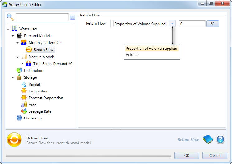
This refers to the amount of water that returns from the water user back to the system. This could be irrigation runoff, rainfall runoff or return flows from a wetland. Double-clicking the demand model enables the return flow editor. The IQQM model includes a number of parameters which determine the volume of return flow (IQQM crop demand model 2). For all other models, the return flow volume is defined either as a percentage of the volume supplied to the demand model. These parameters are common for all the other demand models and can be defined by expanding the model and choosing Return flow (Figure 3).
Figure 3. Water User Node, Demand (Return flow)
Demand distribution
Select Distribution to specify how water is supplied to the water user. This is important when the water user:
- is connected to multiple supply points; and/or
- has a choice of accounts against which orders can be placed.
Select Account Sharing if the water user needs to place orders or extract water via accounts. This is only available if a resource assessment system has been defined (see Resource assessment). The default setting is Non-Account Sharing.
Distribution parameters define how orders will be distributed. Redistributions may occur if an account becomes restricted or if pump capacity is exceeded at a supply point node. The /wiki/spaces/SD35/pages/57872279 contains additional information on this topic.
Non-Account Sharing (Figure 2) is used when accounting is not required. It specifies what proportion of orders and extractions should be assigned to each Supply Point node. If there is more than one supply point, you can define different priority levels for those points using the Priority parameter. Priority 1 is the highest level. All demand is assigned to supply points with priority 1 until the pumping capacity of those points is exhausted, after which priority 2 accounts are used, and so on. If there are multiple accounts at the same priority level, the demand distribution parameter defines how orders are distributed between those accounts.
You can also edit the cells in the Demand Distribution column which define the relative proportion of the water user’s order that should be assigned to the corresponding supply point. You are responsible for ensuring that for elements with the same priority, the demand distribution sums to 100%.
Account Sharing (Figure 4) is used when the distribution of demand to supply points is governed by accounts. It contains an Account Distribution table and a Supply Points table.The former table shows how resources are dsitributed among accounts. The latter displays how water is shared amongst accounts at each supply point node.
Figure 4. Water User node (Distribution, Account Sharing)
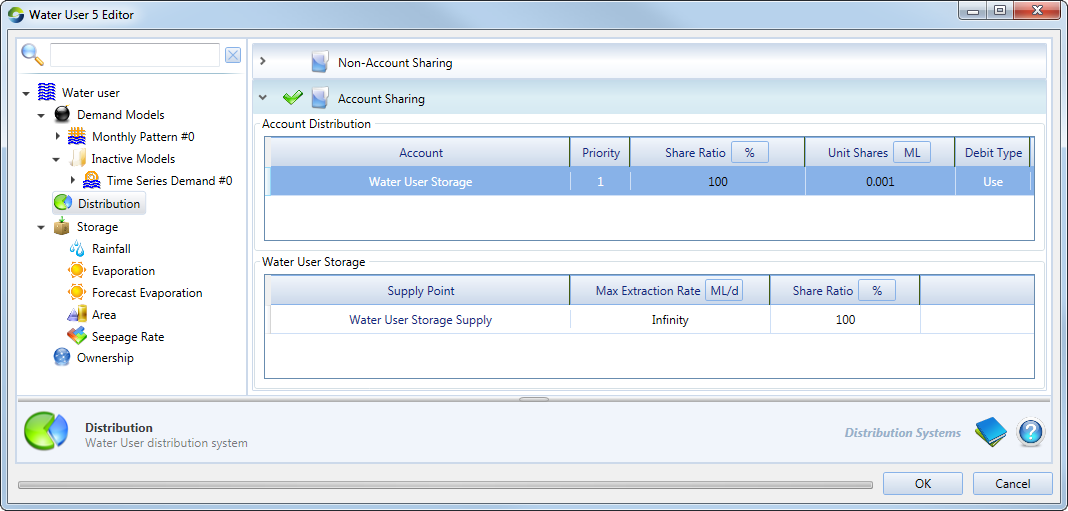
The following parameters constitute the Account Distribution table:
- Account - populated automatically with the names of the water user’s accounts. The links between the Water User node and its accounts can be created in the Resource Assessment Explorer. See Adding Accounts;
- Priority - controls the order in which demands are assigned to the various accounts. Priority 1 is the highest level. All demand is assigned to accounts at this level until the accounts are exhausted, after which priority 2 accounts are used, and so on;
- Share Ratio - allows you to control the relative proportions of demand assigned to accounts at the same priority level. You are responsible for ensuring that ratios for each priority level sum to 100%;
- Unit Shares - displays the number of shares that the account has in the resource assessment system; and
- Debit Type - indicates whether the account has been configured for Order or Use.
The last two columns are populated automatically and are not editable.
The Supply Points table contains the following parameters for each supply point node:
- Max Extraction Rate displays the maximum rate of extraction for the supply point; and
- Share Ratio shows the proportion of the account’s orders that have been assigned to this supply point. Note that while Source evenly distributes the available pump capacity between all accounts which use that supply point, the extraction capacity is assigned to accounts based on priority level. For example, if there is only one account at priority level 1, then that account has full access to the pumping capacity of the supply point.
Simulating on farm storages
Right-click Storage and choose Enable (Figure 5) to simulate on farm or other off-stream storages, which can be used to supply demand to the model. Additionally, in case of any shortfalls in the demand model, the OFS can be used to source additional water (if it is available) to balance this shortage. These storages can also behave like an additional demand model within the Water User node. In this situation, the Water User node generates demand to fill the storage to the required level. The configuration parameters are summarised from Tables 1 to Table 6.
Figure 5. Water User node (on farm storage)
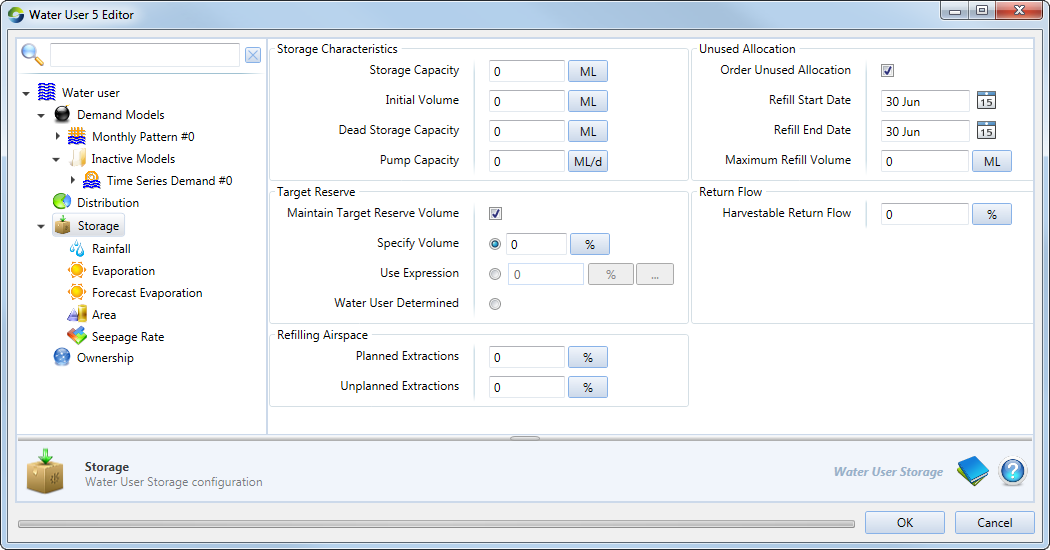
Table 1. Water User node (OFS, Refilling Airspace).
| Parameter | Type | Description |
|---|---|---|
| Planned Extractions | % | The percentage of storage capacity which will be retained as airspace when filling the storage during the Refill Start Date and Refill End Date. |
| Unplanned Extractions | % | The percentage of storage capacity which will be retained when filling the storage with overbank, off Allocation, or regulated water. This airspace is also used to limit Off Allocation requests from the storage. |
Table 2. Water User node (OFS, Target Reserve)
| Parameter | Type | Description |
|---|---|---|
| Maintain target reserve volume |  | Check to maintain the storage at the targeted reserve volume. If storage is below the target, no water will be made available to the demand model unless there is a shortfall in delivering ordered water. Water that is available to order is considered to be above the target reserve. During regular operation, the water user will not plan extractions from the OFS to meet demand that will take it below the target reserve. |
| Options |  |
|
Pump Capacity governs the rate at which water can be pumped into a storage. The extraction rate from a storage is assumed to be unlimited.
To specify the refilling period for ordering unused allocation, enable the Order Unused Allocation checkbox and set the limits of the refilling period using the Refill Start Date and Refill End Date fields. For example:
- a start date of 30 June and an end date of 30 September is a three month period, but
- a start date of 30 September and an end date of 30 June is a nine month period.
Within each date-of-refill field, you can perform the following actions:
- Click the day sub-field to select the day, and type the numbers;
Click the month sub-field to change the month. Although the month is displayed as a three-character abbreviation of the name of the month, you can type over with one or two digits representing the ordinal of the month (1..12); and
Click the date picker icon on the right of the field to display a standard date picker where you can make selections (see Working with date-pickers) (Note that only the month and day values are relevant; years are ignored).
You can supply climate data to the water user storage model as a single value, a time-series file (using Data Sources), or an expression (using the Function Editor). The following items in the list can be configured:
- Evaporation (Figure 6) is used to specify the evaporation rate in millimetres per day to be applied during the flow distribution phase;
- Rainfall (Figure 7) is used to specify the evaporation rate in millimetres per day to be applied during the flow distribution phase; and
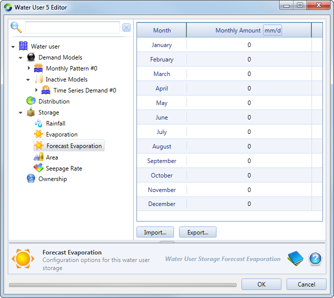
- Forecast Evaporation (Figure 8) is used to define the evaporation rate to be assumed during the order phase as the model calculates the orders required to fill the storage.
Figure 6. Water User node (Storage, Evaporation)
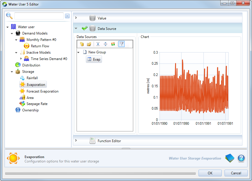
Figure 7. Water user node (Storage, Rainfall)
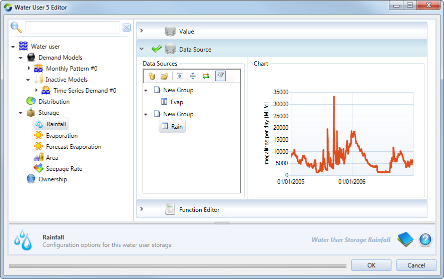
Figure 8. Water User node (Storage, Forecast Evaporation)