Wetlands
Description
A wetland is a complex hydrological unit with features including a connection between a water source and a water body or storage. Wetlands may have ecological, recreational, cultural or consumptive requirements and thus behave in a similar way to some functions of the water user node. In some systems, wetlands consist of several storages that are connected using wetland links. In others, a wetland can connect directly to a main river channel.
Cells model
Source uses a cells model that represents wetlands as a number of storage cells with the movement of water between them described by a set of functions and boundary conditions. Cells are wetland compartments in which water can be stored. They have a relationship between reduced level and surface area that represents the spatial distribution of water in a wetland. Boundary conditions are points at which water can flow in or out of the cells model. In Source, these points occur at either a hydraulic connector or storage inflow or outlet (connected to standard outflow links). The method for determining outflow rate at the boundaries of a wetland cluster will depend on the type of node that is at the boundary:
- For hydraulic connectors, mass balance is calculated as: Outflow is the difference between inflow and conveyance flow.
- For storages:
- If the storage has reached its target level, outflow must be set so that the storage remains at the same volume where possible;
- Outflow is determined by unconstrained orders and spill, but also limited by the total outlet capacity of the storage (which varies with water surface elevation); and
- There a minimum amount ‘spilled’ (ie. when there is at least one spillway). This also varies with water surface elevation.
Wetland cluster
A wetland cluster is a group of wetland storage nodes and hydraulic connectors connected by wetland links, bounded at a hydraulic connector node or storage with either standard inlet/outlet connection(s) or a single wetland link. The hydraulic components of elements within a wetland cluster interact with each other.
Each wetland cluster component is represented in Source as follows:
- The hydraulic connector node represents a boundary condition;
- A wetland link is a connector; and
- A wetland storage is characterised as a cell.
Wetland Hydraulic connector node
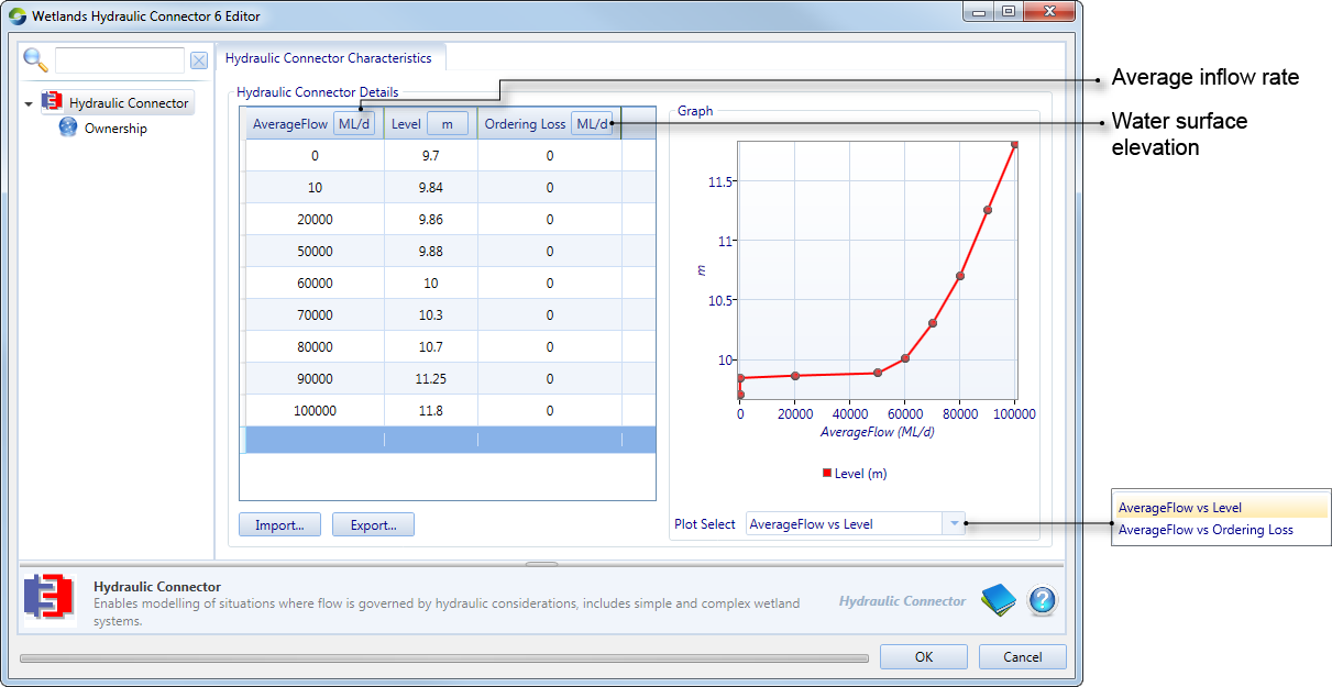
The wetland hydraulic connector node connects wetlands directly to the main river network (ie. not at a storage). This node distributes flows between the main river system and the wetland system. It represents a boundary condition for the connected wetland cluster with a configured reduced level (surface water elevation) versus flow rate relationship. You can import this relationship as a .csv file or enter it manually.
Figure 1. Hydraulic connector node
Wetland storage
Essentially, a wetland storage models a pool of water connected to one or more wetland links. In many cases a weir (modelled as a storage) connects directly to a wetland via a wetland link. Hence the existing storage node is used to implement wetland link connections. Storage volumes, levels and flows are first estimated, then recalculated using the standard Source storage model. The aim of this additional storage model run is to interface between the cells model and the rest of the river system model. When running the storage model, accumulated wetland link flows to/from the storage are treated as a lateral flux – ie. in the same way as seepage and net evaporation. This has the same effect as treating the wetland link as an inflow, or a priority zero outlet (ie. an outlet with higher priority than all others). Storage releases that go down standard links are taken into account in cell model storage and wetland link calculations, but these are an approximation based on combined outlet capacity and orders. Outlet path priority is not considered for this purpose.
To implement the wetland storage as a regular storage, it is assumed that:
- All links are at the wall (storage is a level pool); and
- Storage capacity volumes are > 0.
In Source, re-regulating storages generate orders to upstream storages to maintain target operating levels or meet downstream requirements. If there is no upstream storage connected to the wetland storage inlet via standard links, it will be treated as a headwater storage. Hence when no inlets are connected, order generation and accounting functionality are not used.
Similarly, it is only possible for downstream water users to place orders on wetland storages where the water user is connected to the wetland storage outlet via a path of standard links. Owner shares, internal spilling/ceding, borrow and payback arrangements are only relevant in these cases.
Wetland Link
Wetland links use a hydraulic model and are used to connect storages within a wetland, or a wetland to a river. There are different types of wetland links available, each reflecting variations in hydraulic properties - eg. conveyances, weirs, pumps and culverts. Wetland links can be either regulated or unregulated, uni-or bi-directional, and you can configure which end of the link will have a higher reduced level.
Use the link's feature editor to configure each of these parameters:
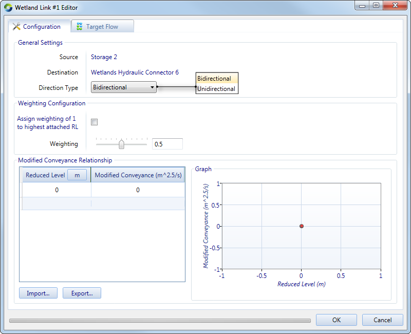
- The Configuration tab (Figure 2) is used to specify the direction type and weighting. The latter refers to the head height at each end of the link. It is the weighting applied to the head height and adjustments to this value are important if there were a significant height difference between the wetland head height and the river head height. If RL1 is the Connector side and RL2 is the wetland side of the link, a weighting of 0.5 is the average of the head height of RL1 and RL2. If 0 were used instead, the head height of the connector would be used to work out the reduced level to determine the direction of the flow of water and if 1 were used, the wetland head height would be weighted; and
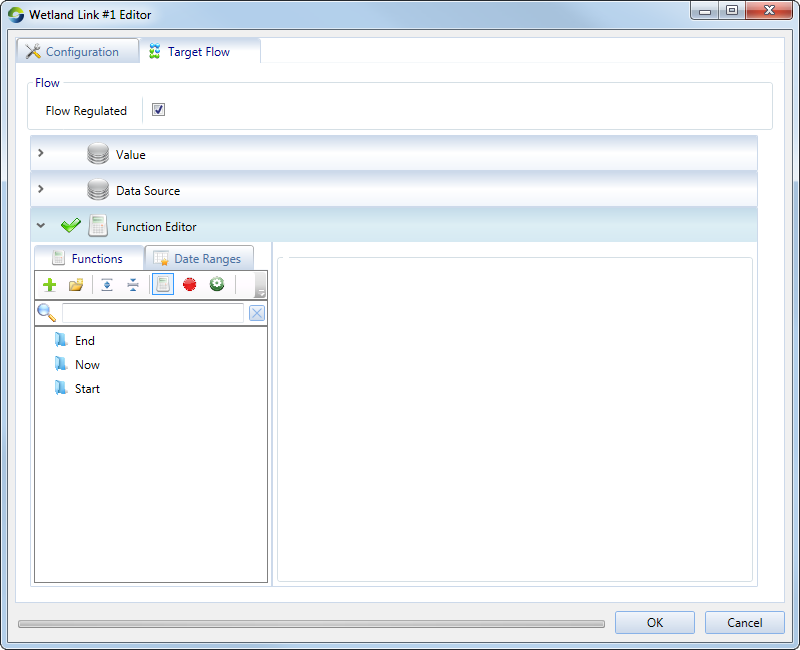
- The Target flow tab (Figure 3) is used to specify whether the link is regulated or not (using the Flow Regulated checkbox) and to allocate a time series to the flow
Figure 2. Link (Wetland, Configuration)
Note that a conveyance link is a type of wetland link used in Source. The discharge across the link depends on the hydraulic conveyance (relationship between reduced level and discharge) of the link and hydraulic head difference between the two ends of the link.
Figure 3. Link (Wetland, Target flow)
Ordering at wetlands
In the order phase, wetland clusters can both generate orders (directly or indirectly) and supply them:
- Direct order generation: Each storage in a wetland can have a target level or range and place orders to ensure the storage remains at the level or within the range; or
- Indirect order generation: Water users may be used to generate demands for a wetland cluster that are translated into orders at supply point nodes. For example, a water user may use an ecological demand model to generate a demand. The order associated with this in-stream requirement would enter the system at a supply point node immediately downstream of a wetland cluster.
Viewing wetland results
In the Recording Manager, select the following attributes to view the output of the different components of a wetland:
- Cell: Storage type, Storage Level attribute for a wetland storage;
- Boundary condition: Wetland Hydraulic Connector type, Average Reduced Water Level attribute for node-related results; and
- Connector: Wetland Link type > Average Flow Rate attribute (Figure 4) - the bidirectional link (red) shows that as the storage level decreases, there is an increase in the water flow through the wetland link from the connector to the storage. There is also a flow back to the connector from the storage if the head level in the storage is higher than the head level at the connector. The unidirectional link (blue), shows that the flow is one way, ie. there is a flow only into the storage from the connector and no flow from the storage to the connector. Hence the values are all above zero.
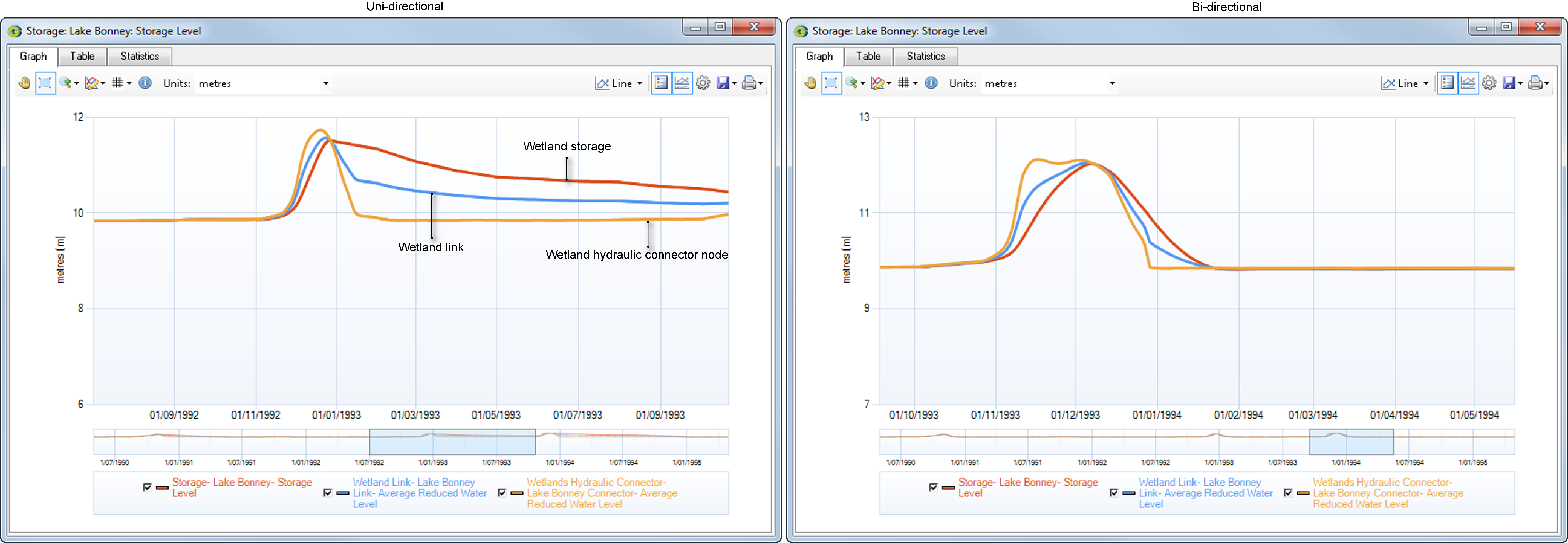
Figure 5 shows how water level for a wetland storage, link and the hydarulic connector node differs between a uni-directional (left) and bi-directional (right) link. For a uni-directional link, as the level in storage increases, there is a gradual drop in the average reduced water level, which in turn reduces the amount of water flow through the link into the storage. This process is gradual because the water can also go from the storage side to the connector side if there is a drop in connector head level. In a bi-directional link, the drop in average reduced water level of the connector and the wetland is steeper because a reduced head in the river level will stop water flowing into the wetland but will also stop water from flowing back into the river from the wetland due to the wetland link being unidirectional. The wetland link water level gradually reduces after a steep fall as the head level in the storage reduces.
Figure 4. Wetland link (Results)
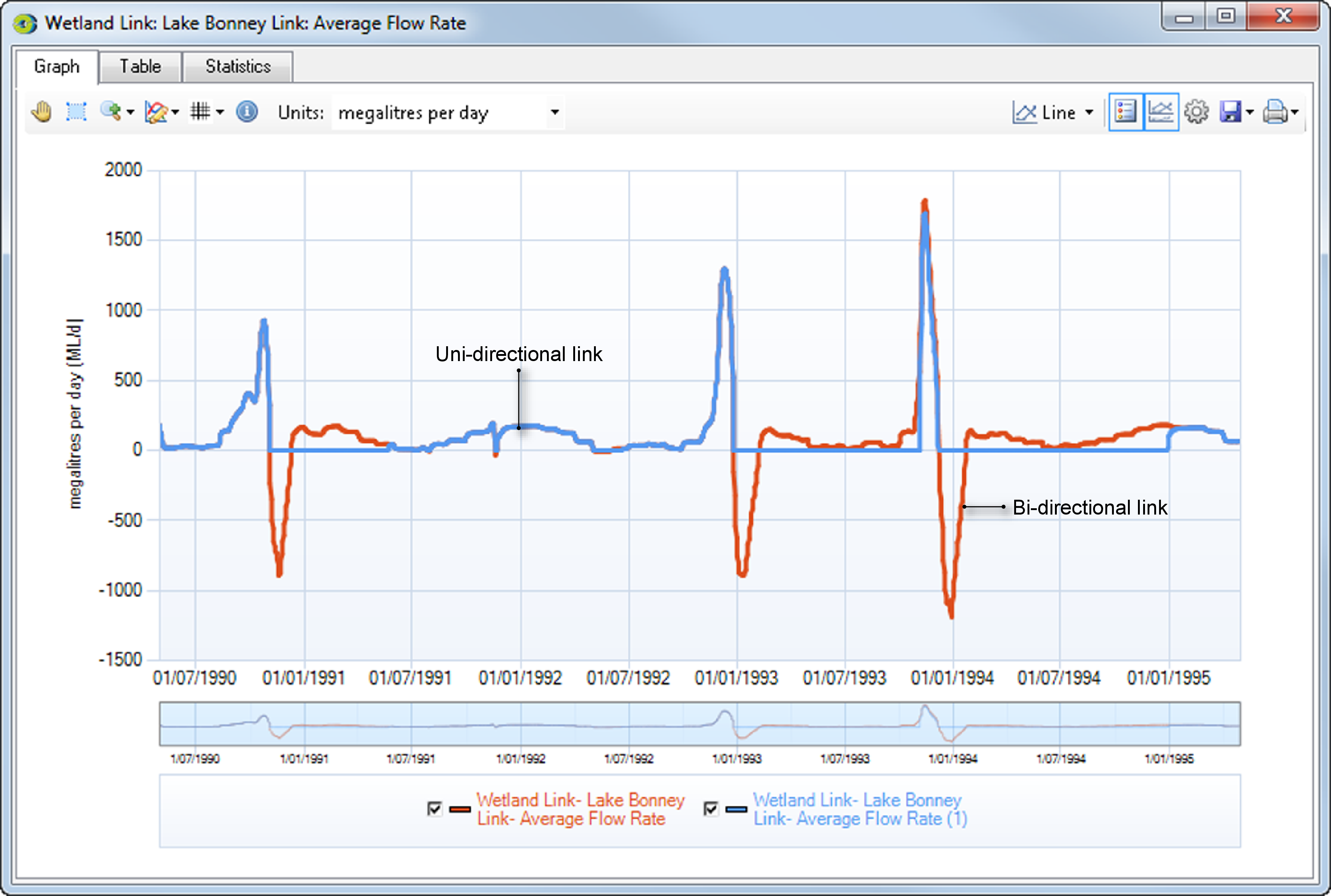
Figure 5. Wetland results (Uni-directional vs Bi-directional)