Note: This is documentation for version 4.11 of Source. For a different version of Source, select the relevant space by using the Spaces menu in the toolbar above
Hydropower - SRG
Hydropower is modelled as a combination of a downstream hydropower demand, a hydropower release, and the energy that is subsequently generated by this release.
- The hydropower demand is represented in the model as a water demand at the turbine(s).
- When the storage is not spilling the hydropower release is the release from storage required to meet the hydropower demand; this will be a combination of the releases made to meet all downstream demands. When the storage is spilling there are options for how much is released through the hydropower valve; it may be none, as much as possible or up to all downstream orders.
- Hydropower generation is the energy generated and is a function of the discharge through the turbine, head, turbine efficiency and time.
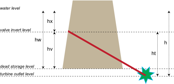
Turbines are assumed to be attached to storage outlet valves (as shown schematically in Figure 31) and there may be more than one turbine associated with each outlet. It is possible to configure storages with multiple outlets that could include multiple valve outlets with turbines.
Figure 31. Estimation of total head to turbine outlet
Scale
This node represents a location and can therefore be considered to be site scale. It is used at every model time step.
Principal developer
eWater CRC
Version
Source v3.8.8
Dependencies
Hydropower is one of the features associated with the storage node.
Availability/conditions
Automatically included with the product.
Flow phase
Calculation of hydro-electric energy generated
The energy generated is a function of the discharge through the turbine, total head (see Figure 31) and turbine efficiency over the time step. The turbine efficiency is assumed to be constant for a given discharge and head, which is a simplification. The calculation of energy generated, in megawatt hours (MWh), during each model time step is:
Equation 130 | 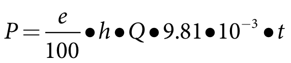 |
Where
P the energy generated (MWh)
e the turbine efficiency (%)
h the average total head to the turbine outlet during the model time step (m)
Q the average discharge through the turbine during the model time step (m3/s)
t is model time step (h)
The total head, h, is evaluated by Equation 131, where the terms are defined as shown in Figure 31:
Equation 131 | 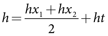 |
Where
hx1 the head above the valve inlet at the beginning of the time step (m)
hx2 the head above the valve inlet at the end of the model time step (m)
ht the head difference from the valve inlet to the turbine outlet (m)
It should be noted that this formula is a simplification as the energy should be estimated by integrating Q and h across the time step. Given that the change in head and discharge during the time step can be expected to be small this is a reasonable approximation.
Calculation of discharge through turbines
The storage node calculates storage release in response to storage demand, subject to outlet constraints such as the maximum release for each valve. The storage release represents the water that is controlled release as well as water that spills, and may occur through a combination of culverts, pumps, valves, gated spillways and ungated spillways. The storage demand represents the total of all downstream demands. The maximum release curve for each valve is entered in the form of a storage-discharge relationship and comprises part of the total minimum and maximum release curves.
The discharge through the turbines is calculated each model time step using one of the following three options:
1. Do not generate from spill: 
2. Generate using spill: 
3. Generate using spill; up to downstream orders (IQQM Mode): 
Where the  refers to the capacity of valves with turbines, as defined by the applicable turbine release curve for the head at the current time step.
Prioritisation/scheduling of turbines
The assumption is that any storage release to meet downstream demands of whatever type will occur through the turbines first, on the basis that hydropower would be generated to meet hydropower demands whenever possible. If the hydropower demand exceeds the sum of turbine outlet capacities then all turbines are assumed to be operating. However, if the hydropower demand is less than the sum of turbine outlet capacities than a decision needs to be made about what turbines are operating. The assumption is that highest generation potential gets priority. Priority is evaluated considering head and efficiency as in Equation 132, below. The highest value will get the highest priority and so on until the demand is satisfied.
| Equation 132 | 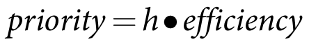 |
Prioritisation is illustrated in the Two Turbine Example below.
Single Turbine Example
A storage has one valve, which is connected to a turbine. The turbine has a head difference (ht) of 100 m and an efficiency of 80%. The storage has a head (hw) of 260 m above dead storage and the valve invert (hv) is 10m above dead storage. Based on the definitions in Figure 31:
| Equation 133 | 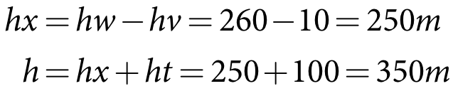 |
The head drawdown is assumed to be negligible during the model time step which is one day. Therefore, from Equation 131:
| Equation 134 | 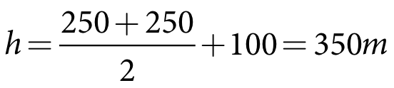 |
At 350 m head the turbine can potentially let out 100 m3/s but the total demand in the current time step is only 50 m3/s; hence the required discharge through the turbine is 50 m3/s and from Equation 130 the energy generated is:
| Equation 135 | 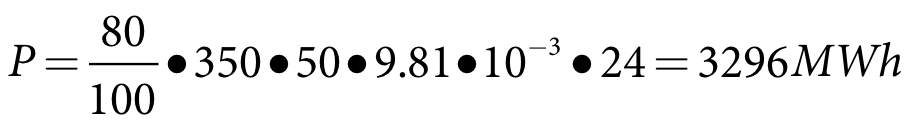 |
Two Turbine Example
A storage has a head (hw) of 260m above dead storage. The storage has two valves, both connected to turbines. The head drawdown is assumed to be negligible during the model time step which is one day.
Turbine1 has a head difference (ht1) of 100 m and an efficiency1 of 80%. The valve invert (hv1) is 10 m above dead storage. Based on the definitions in Figure 31:
Equation 136 | 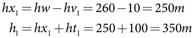 |
Turbine2 has a head difference (ht2) of 50 m and an efficiency2 of 90%. The valve invert (hv2) is 20 m above dead storage. Based on the definitions in Figure 31:
| Equation 137 | 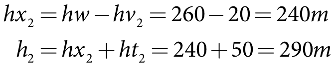 |
Therefore, from Equation 131:
Equation 138 | 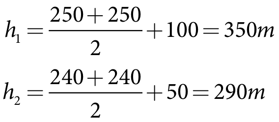 |
At 350 m head, turbine1 can let out 100 m3/s while, at 290 m head, turbine2 can let out 50 m3/s; the combined potential discharge is 150 m3/s. However, the total demand in the current time step is only 125 m3/s. Therefore the required discharge through the two turbines is 125 m3/s and utilisation of the two turbines needs to be prioritised.
Turbine priority is calculated using Equation 132 as follows:
Equation 139 | 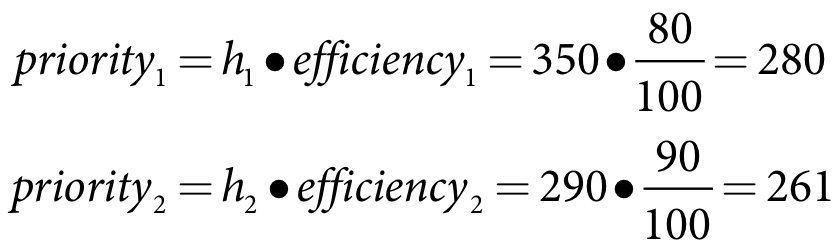 |
Priority1 is greater than priority2, therefore turbine1 has priority. Turbine1 is fully utilised first with 100 m3/s, which leaves turbine2 with:
| Equation 140 |  |
From Equation 130 the energy generated is:
Equation 141 | 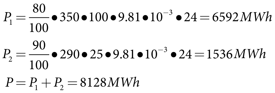 |
Key assumptions and constraints
Assumptions:
- Turbine efficiency is assumed to be fixed whereas in reality it is a function of head and flow rate.
- The energy calculation is not integrated across the time step as it is assumed that the change in head will be small. There may be cases where this is not true.
Constraints:
- Sub-time-step releases and energy calculations are not accommodated. These can be modelled by reducing the model time step or assuming the peak demand is averaged across the time step.
Data
Input Data
In addition to parameters needed to define storage characteristics (Storage node SRG), the following need to be specified for modelling hydropower:
- The option for calculating the discharge available for hydropower generation at each time step.
- Turbine release curves.
Output Data
Hydropower generated at each time step is recorded.