Note: This is documentation for version 4.11 of Source. For a different version of Source, select the relevant space by using the Spaces menu in the toolbar above
Tank
Introduction
A tank is a type of storage used in domestic, commercial and/or industrial settings to store water collected from surface runoff or sources such as greywater or blackwater waste streams. Once stored the water can be released in a controlled manner, and/or used to supply water demands.
There is a trend towards installing domestic rainwater tanks in urban areas to capture roof runoff and supply non-potable water demands. The benefits of using water sourced from a rainwater tank include:
- reduced reliance on potable water supply, thus deferring potable water system upgrade or expansion and increasing the security of supply from existing water sources;
- stormwater retention/detention;
- urban water quality improvement via retention and diversion of stormwater to the sewer and garden areas, thus reducing the volume of stormwater pollutants discharging to the catchment watercourses; and
- protection of urban streams, through reducing the duration of elevated flows.
Rainwater tanks are most efficient when the retained water supplies multiple water demands within a household, eg toilet flushing, garden irrigation, filling or topping-up swimming pools, clothes washing and other appropriate non-potable uses.
In many areas health departments do not expressly prohibit rainwater tanks supplying drinking water, however, guidelines typically recommend avoiding drinking rainwater where a reticulated potable supply is available.
Tank construction
Rainwater tanks are usually constructed from plastic, or galvanised steel, and are located above-ground adjacent to the sides of a dwelling or building. Where space is limited, tanks can also be installed below-ground, under-floor and in-slab - in these situations, tanks are often constructed from concrete or impermeable plastic membranes.
Conceptualisation
Conceptually, the operation of a rainwater tank is identical to the operation of any tank-based storage infrastructure. The simulation scheme developed is generic in its applicability to all forms of tank-based storage. The tank allows for the inflow of rainwater as well as the provision of trickle top-up, triggered to start and stop at a user-specified tank level.

Contents
Restrictions
There are restrictions on which node inputs and outputs you can connect together. See Urban Developer node connection rules.
The Tank node is available for Urban Scenarios only.
Multiple Tanks
In the current version of Urban Developer, you can connect more than one tank to a supply point; however this model type is not currently supported and may give inaccurate results. If you need to model a multiple-tank installation, the best workaround is to regard the entire installation as a single tank, and adjust initial levels, first-flush volumes etc, accordingly.
Node Dependencies
- Inflow: Tank inflow is usually from a roof node or other impervious area.There is no direct input capability for "topping-up" the tank; topup is controlled by a parameter in the tank property editor (see below).
The top-up function takes water from the mains supply, however in this version, the mains supply usage due to trickle top-up is not tracked.
Node Outputs
- Demand: The tank volume extracted by a Water Use node per unit time.
Link type: Demand - Spill: The volume flowing out of the tank when the detention volume is exceeded.
Link type: Runoff (this link type is not currently implemented in the Urban Developer Plugin) - Detention outflow: The flow from the overflow pipe at the invert of the detention volume, during a flood event.
Link type: Runoff (this link type is not currently implemented in the Urban Developer Plugin)
Node Properties
The tank parameters must be configured to represent the total number of dwellings in downstream Average or Behavioural Water Use nodes. For example, 4 houses with 10 m3 of tank volume each would need to be attached to a single tank node with 40 m3 total volume.
| Property | Description | Units | Default Value | Recommended Range | Constraints | ||||||
|---|---|---|---|---|---|---|---|---|---|---|---|
| Cross-sectional area | Defines the cross-sectional or area of the tank base. | m2 | 2.5 | NA | >= 0 | ||||||
| Height | Defines the total height of the tank. Includes detention and dead zone height and dead zone height. | m | 2 | NA | >= 0 | ||||||
| Height of off-take invert | Defines the height of the offtake pipe on the tank; the offtake pipe supplies demands from the tank. The invert level of the offtake is the height of the lowest point of the pipe above the tank base. Once the tank is filled above the offtake invert level, the water depth in the tank will never fall below this level. Demand off-take occurs from the base of the tank just above the anaerobic or "dead" zone; a tank should therefore have a minimum "dead zone" depth of 0.1 m to allow for accumulation of sediment and other material. Water will never be drawn from the "dead zone". | m | 0.1 | [0, 2] | >= 0 | ||||||
| Initial water depth | Defines the initial depth of water in the tank at the start of the model run. | m | 0.1 | [0, 1000] | >= 0 | ||||||
Overflow Configuration | |||||||||||
| Detention volume depth | Defines the detention (storage) volume depth of the tank. The detention volume depth is the depth from above the overflow outlet invert to below the tank spill/top of the tank; hdet in the diagram. Detention volumes are used as buffers to decrease output flow rates in situations of high input flow. If the tank has no detention storage, set the detention volume depth equal to the overflow outlet diameter. | m | 0.1 | NA | [0, 2] | ||||||
| Overflow outlet diameter | Defines the diameter of the overflow orifice, located at the base of the detention storage. | mm | 100 | [10, 320] | [1, 1000] | ||||||
| Overflow outlet discharge coefficient | Discharge coefficient used in the evaluation of the orifice flow equation. | NA | 0.86 | NA | NA | ||||||
External top up | |||||||||||
| Enable external top-up | If enabled, allows for the tank to be topped-up with mains water so that the tank always maintains a user-specified water level. You do not need to connect a mains water supply node to a tank node to provide inflow for top-up; when you enable external top-up, Urban Developer handles the mains connection internally. | NA | Disabled | NA | NA | ||||||
| Top-up rate | Defines the rate of mains water top-up in litres per second. | L/s | 250 | NA | >= 0 | ||||||
| Top-up triggered on | Defines the depth above the tank base at which the tank will start to top up. This depth must be greater than the height of the off-take. | m | 0.2 | NA | >= 0 | ||||||
| Top-up triggered off | Defines the depth above the tank base at which the tank will stop automatically topping up. This depth must be greater than the Top-up triggered-on depth. | m | 0.3 | NA | > Top-up triggered on | ||||||
First Flush System | |||||||||||
| Enable first flush system | If enabled, changes the tank inflow behaviour so that a user-specified volume of water will bypass the tank before inflow to the tank occurs. | NA | Disabled | NA | NA | ||||||
| First Flush Volume | Specifies the volume of water the first-flush device diverts. | m3 | 0.015 | [0, 100] | >= 0 | ||||||
| First Flush Outlet flow rate | Specifies the outflow rate to the selected discharge outlet. | m3/s | 0.01 | NA | >= 0 | ||||||
| Discharges Connection | Specifies the tank outlet that first-flush outflow is discharged through. Detention outflow specifies that the first flush volume discharges via a connection to the detention outflow pipe. Spill specifies that the first flush volume discharges via spilling from the tank. | NA | NA | NA | NA | ||||||
Other | |||||||||||
| Tank bypass | Not currently implemented in the Urban Developer Plugin. If enabled, all inflows flow directly to the detention outflow. This allows you to temporarily disconnect a tank without removing it from the model. | NA | NA | NA | NA | ||||||
User Interface
The Tank node is configured via the node Feature Editor.
Tank Technical Details
First Flush Separation
First flush separation is a commonly applied practice in many rain and stormwater harvesting systems. First flush devices are typically used to separate the initial runoff from a surface from subsequent flows and operate on the principle that the initial runoff commonly contains a higher proportion of accumulated surface contaminants, such as dust, sediment, litter, animal droppings, leaves and debris.
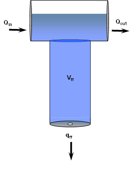
There are many forms of first flush separation devices. The storage tank configuration utilised by Urban Developer incorporates a simple volumetric first flush model conceptually illustrated in Figure 1. The device, shown in Figure 1 operates by allowing the first flush to fill a storage chamber, drained by a small orifice. Once full, inflow bypasses the storage chamber and leaves the device via the outflow pipe. Once rainfall ceases the first flush storage chamber is drain slowly as water leaves via a small orifice located at its base. For simplicity, the discharge is assumed to be at a constant rate.
Figure 1: First flush system.
 where
where
Qin is the inflow volume (m³);
Qout is the outflow volume following first flush separation (m³);
qff is the constant outflow rate from the chamber (m³/s); and
Vff is the diameter of the first flush outlet (m³);
The Storage Tank
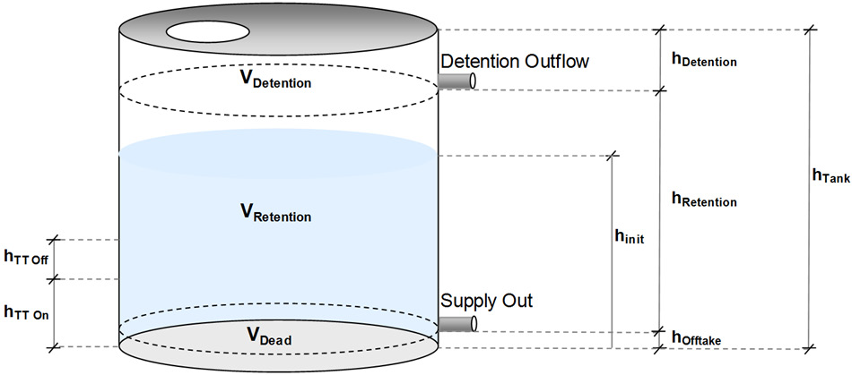
The Urban Developer storage tank, shown in Figure 2, breaks the available storage volume into three distinct storage zones.
Figure 2. Urban Developer storage tank definition.
where
VDetention is the Detention Storage Volume (m³);
VRetention is the Retention Storage Volume (m³);
VDead is the Dead Storage Volume (m³);
hoff-taker is the height of the supply off-take obvert from the base of the tank (m);
hretention is the height of the retention storage volume (m);
hdetention is the height of the detention storage volume (m);
htank is the height of the storage tank (m);
hTT On is the height of the trickle top-up on trigger (m); and
hTT Off is the height of the trickle top-up off trigger (m).
“Dead storage” or the “anaerobic zone” is located at the base of the tank and is typically provided for the accumulation of sediment and other material. Dead storage is defined by the height of the supply off-take and once filled cannot be utilised within the model to meet any form of demand.
Retention storage is the volume of the water held above the supply off-take but below the detention outflow. Retention storage can be used to supply consumptive demands within an Urban Developer model.
A portion of the total tank volume can be specified to as detention storage by setting the detention storage depth and defining the detention outflow orifice characteristics. Detention storage can be used to mitigate peak inflow events by storing and releasing water at a rate less than that of the inflow.
Tank Routing
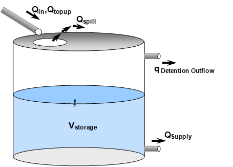
The Urban Developer storage tank allows for the inflow of water, Qin, as well as providing for an optional trickle top-up volume, Qtopup, that is triggered on and off at user-specified tank heights. Supply to meet consumptive demand, Qsupply is drawn from the base of the tank just above the “dead” storage zone.
Inflows in excess of the retention storage volume are routed through the detention outflow, which is controlled according to the capacity and configuration of the outlet. During periods of very large and rapid inflows the detention storage capacity of the tank may be exceeded resulting in spillages, Qspills, from the top of the tank. This spillage volume represents the volume of water that is unable to enter the storage tank.
Figure 3. Rainwater tank configuration.
The routing algorithm adopted by the tank applies a first order Ordinary Differential Equation (ODE) solution scheme to solve the governing water balance present in Equation 1.
Equation 1

where
Vt is the volume at the end of time interval t (m³);
Vt-1 is the volume at the end of time t-1 (m³);
Qtin is the inflow volume for time interval t (m³);
Qttopup is trickle top-up volume for time interval t (m³);
Qtsupply is the demand volume extracted for time interval t (m³).
ht is the depth of water at the end of time interval t (m)
Qtspill(ht) is the overtopping volume as a function of depth (m³); and
Qtdetention(ht) is the discharge rate from the detention storage for time interval t (m³/s).
Outflow from the detention volume is calculated as a function of depth, above the detention outflow orifice obvert, Outflow using the minimum discharge of the broad crested weir and orifice flow equation 2 to account for the transition that occurs as the outflow orifice is drowned. Definition of the variables presented in Equation 2 can be found in Figure 4.
Equation 2
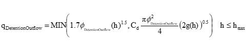
Figure 4. Rainwater tank detention outflow configuration.
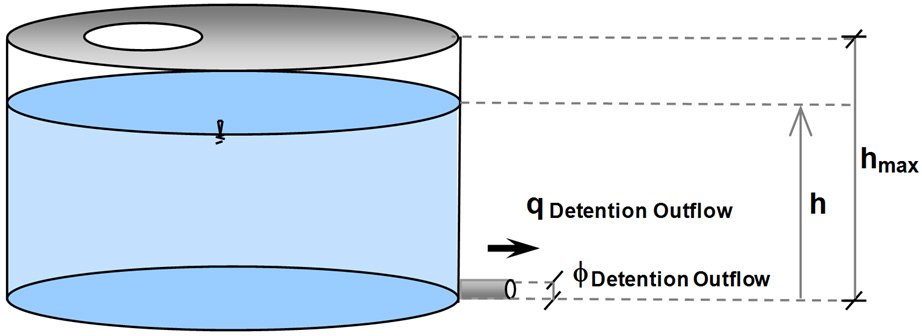
where
hmax is the maximum height of the detention storage (m);
h is the depth of water above the outlet obvert (m);
qdetention outflow is the detention storage outflow rate (m³/s); and
fdetention outflow is diameter of the outflow orifice (m).
Acknowledgements
This material has been adapted from:
eWater Cooperative Research Centre (2011) Urban Developer Product Specification: Storage Tank Routing v0.4. eWater Cooperative Research Centre, Canberra. 23 June 2011.