Note: This is documentation for version 4.11 of Source. For a different version of Source, select the relevant space by using the Spaces menu in the toolbar above
User Interface
Main screen
Once open, you can see that Source follows the user interface conventions of a standard Microsoft Windows™ application (as shown in Figure 1. For example:
- The main window can be maximised or minimised using controls at the right hand end of the title bar;
- A menu bar with familiar File, View and Help menus. Additional menus direct you to more specific functions of Source; and
- Toolbars providing point-and-click access to many commands.
Figure 1. User interface for Source
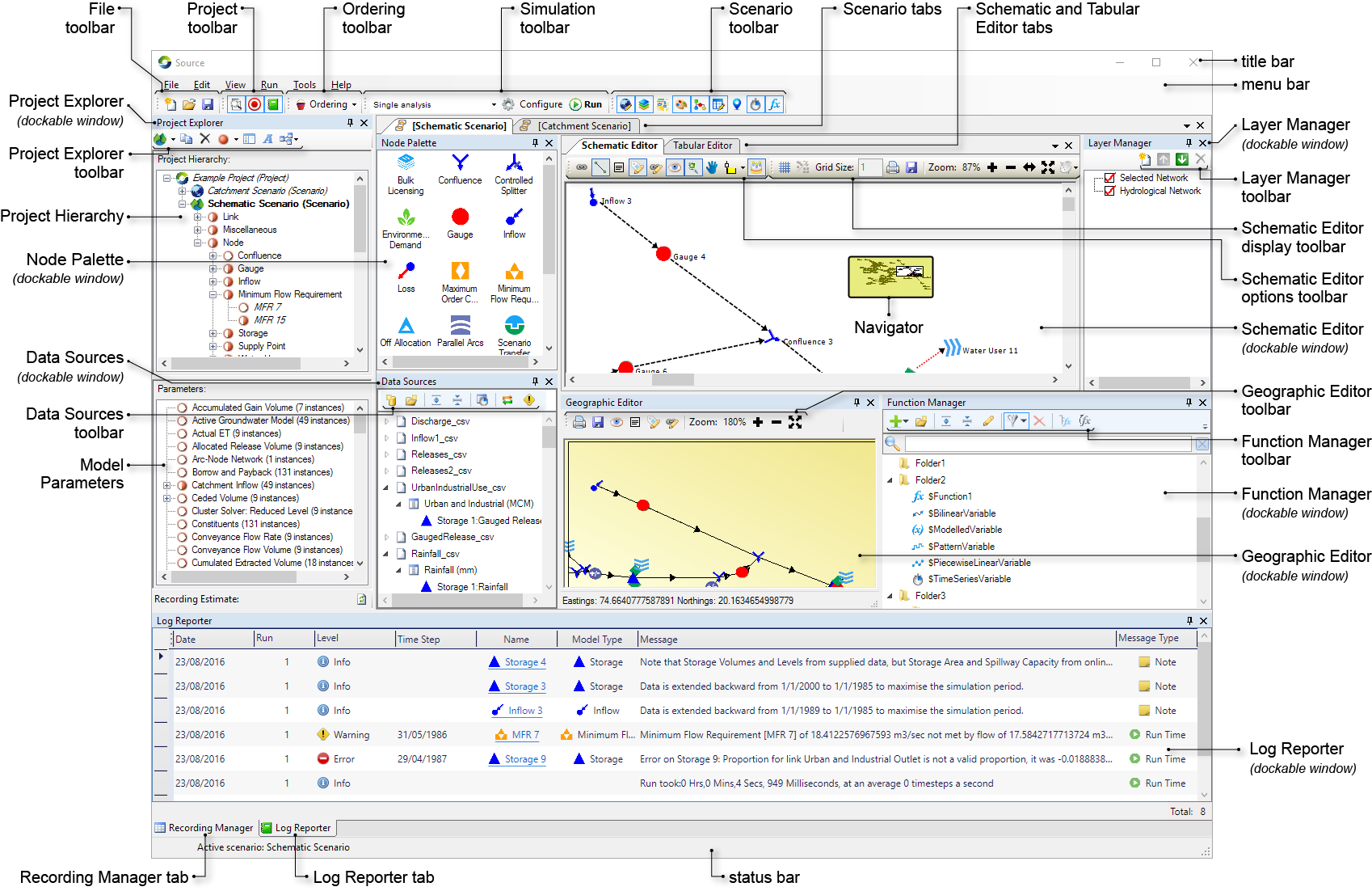
The following toolbars (available from the main Source screen) allow you direct access to various sections of Source:
- Data Sources toolbar - allows you to add and manage sources of data (time series or by linking to another scenario). You can edit or view this data once it has been loaded in the Data Sources Explorer;
- File toolbar - allows you to create a new project, opening an existing project, and saving a project (and all the scenarios within that project);
- Function manager toolbar - allows you to add and manage all functions in Source;
- Ordering toolbar - provides quick access to ordering-related functions. The button on this toolbar reveals a pop-up menu;
- Project toolbar - allows you to toggle view of the Project Explorer, Recording Manager, Log Reporter and Chart Recording Manager;
- Recording Manager toolbar - allows you to manage results in the Recording Manager;
- Scenario toolbar - allows you to hide or display the Geographic Editor, Schematic Editor and Tabular Editor, the Function Manager, Data Sources, the Node Palette, the Layer Manager and Location Control panels; and
- Simulation toolbar - allows you to set the analysis type (single, stochastic or flow calibration), specify start and end dates for the simulation, and to run the catchment model.
Quitting Source
You can quit Source by doing either of the following:
- Choose ; or
Press Alt+F4 on your keyboard.
Projects and scenarios
Projects act as 'wrappers' holding a collection of one or more scenarios. Refer to Projects and scenarios for more information.
Saving your work
Save your work by doing either of the following:
- Choose
- Click Save Project on the File toolbar.
If you have not saved your project previously, choose and you will be prompted to name your project. Source uses the Windows file extension ".rsproj" to identify its project files.
Editors
Source uses editors which are tailored to the needs of the main scenario types. There are three main editors, known as the Geographic, Schematic and Tabular editors, which support the catchments, management and operations scenario types respectively. These editor-scenario type associations are not absolute and you will often use multiple editors within a given project. For example, you can use the Schematic Editor to define the model of a river system for both operations and management scenario types. Details for each of these editors are available at Geographic Editor, Schematic Editor and Tabular Editor. You can also view scenarios on a background map image using the Map tab.
Components of the main screen
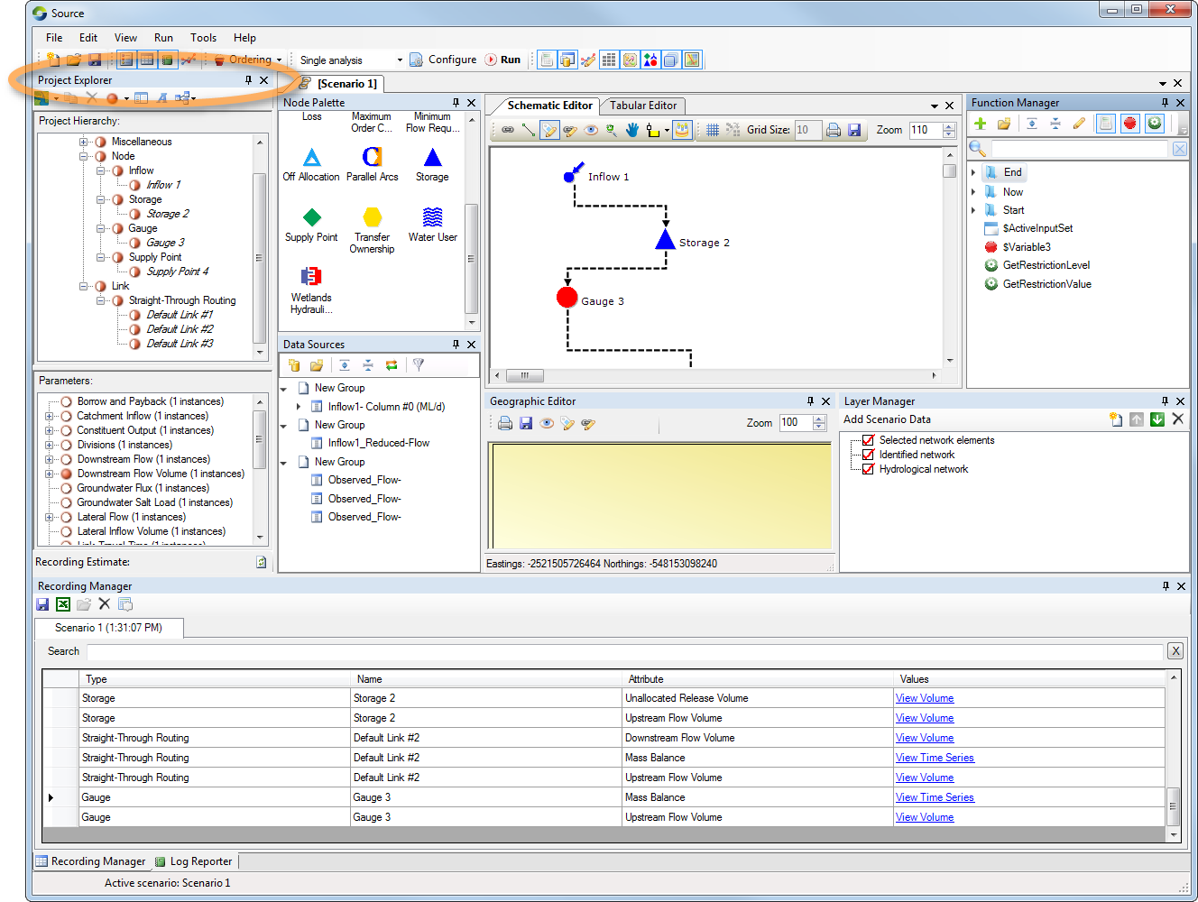
Project Explorer
The Project Explorer (Figure 2) allows you to manage model components using a combination of the menu bar, the Project Hierarchy, the Model Parameters area, and pop-up menus. For an active scenario, clicking an item in the Schematic or Geographic Editor highlights it in the Project Hierarchy.
Figure 2. Project Explorer
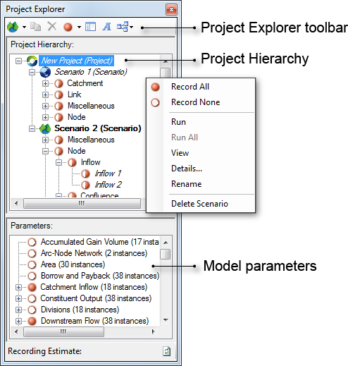
Project Hierarchy
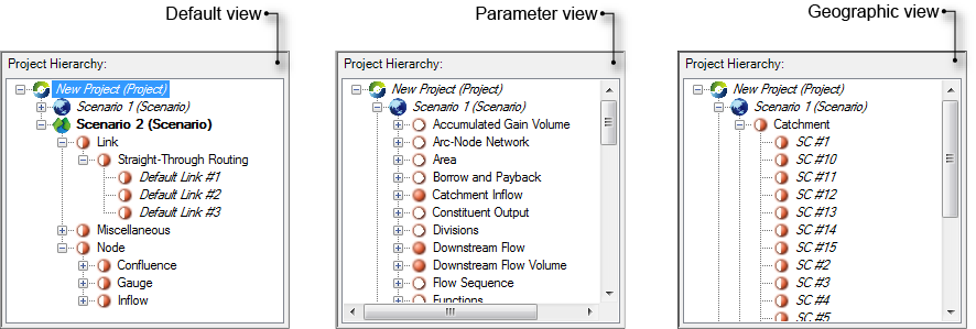
The Project Hierarchy displays a structural breakdown of the project. The type of display will depend on the view selected within the View Type pop-up menu on the Project Explorer toolbar. All view options will display at least the project and scenarios within the project. The Default View, which is shown on the left side in Figure 3, displays individual elements that make up a model. The Parameter View displays all the recordable parameters for the model. The Geographic View displays elements of the geographic scenario.
Using the contextual menu (as shown in Figure 2), for a selected node/link, you can set parameter recording, edit and rename it.
Figure 3. View type menu options
Model parameters
The Model Parameters area (refer to Figure 2) shows which parameters will be recorded for the scenario element (node, link, catchment etc) that is currently highlighted in the Project Hierarchy. The indicators have the following meanings:
 Every parameter at this level and below will be recorded; or
 No parameters at this level and below will be recorded.
 Some (but not all) parameters at this level and below will be recorded.
To change which parameters are recorded, first select an element in either the Project Hierarchy or Model Parameters area, then use either the Recording Options pop-up menu on the Project Explorer toolbar, or the contextual menu to change the setting. Note that these commands are hierarchical in nature and affect both the selected element and its logical children as displayed in the visual hierarchy.
Data Sources
The Data Sources tab allows you to view and manage time series at one location in Source. When time series are added using the Data Sources Explorer, they are available for use throughout Source. For more details on using this, refer to Specifying data inputs.
Function Manager
The Function manager panel allows you to create, manage and maintain all functions defined in Source. Just as all data in the Data Sources Explorer is available throughout Source, all functions added in the Function manager can be used in the same way.
Node Palette
The Node Palette contains a list of icons representing the nodes that are supported by Source. To create a node-link network, drag icons from this palette onto the Schematic Editor’s drawing surface.
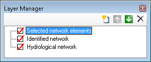
Layer Manager
The Layer Manager (Figure 4) is mainly associated with the Geographic Editor. It is visible by default when you create a new catchments scenario. Choose if the Layer Manager is not visible. You can add new layers, and move layers up and down in order of visibility. The checkbox next to a layer’s name indicates that the layer is visible in the Geographic Editor. Note that any layers that are added or removed are not persisted in the scenario.
Figure 4. Layer manager
Recording Manager
The Recording Manager displays a list of all the recorded results from the model run or runs. Each model run has its own tab. You can sort the results by clicking the column headings. The associated with this window gives quick access to common functions.
Log Reporter
The Log Reporter displays any errors, warnings or information messages resulting from user actions, or events that have occurred when running a scenario. You can choose to display or hide different types of events by clicking the Errors, Warnings, or Info tabs at the bottom of the Log Reporter.
Chart Recording
Chart Recording allows you to compare the results of different scenario runs. You can change certain parameters in a scenario to see how the output is affected. Refer to Chart Recording Manager for more information on this.
Working with the Source window
Just as with standard Microsoft applications, you can adjust panels within the Source window. This provides great flexibility when working with very large models.
About feature editors
A feature editor window allows you to define various parameters for nodes and links. It opens when you double click on components in the Schematic Editor. You can also open a feature editor by right-clicking on the node or link and choosing Edit from the contextual menu.
Each node or link type supports different parameters, so the exact structure of feature editors varies according to the type of node or link being manipulated. However, the controls shown in Figure 5 are common to many feature editors.
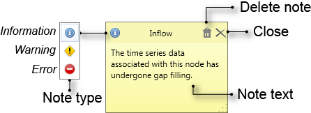
The left panel lists all parameters associated with the node or link. You can also add a note to a node or link to indicate a specific feature for example, which may affect its behaviour during a scenario run. This note is indicated as an exclamation mark on the component's icon in the Schematic Editor. It also appears in the Recording Manager after a scenario run. To include a note, right click on the component's icon in the feature editor and choose Add Note. This is shown in Figure 7.
Contextual menus can be accessed by right-clicking on various elements in the user interface. In some cases, choices in contextual menus duplicate those in toolbars and the main menu structure. In others, the contextual menus are the only way to access a particular function. All contextual menus available in Source are shown with the relevant feature editor or graphic;
Figure 5. Feature editor (common controls)
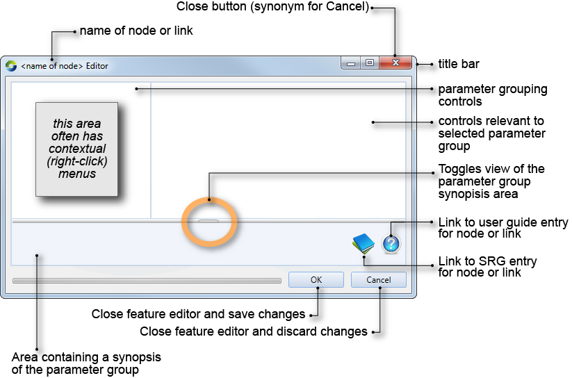
Other behaviour which is shared by a number of feature editors includes:
- Parameters applicable to a node or link may be grouped according to related purposes;
- Some user interface elements are only enabled if their prerequisites have been met;
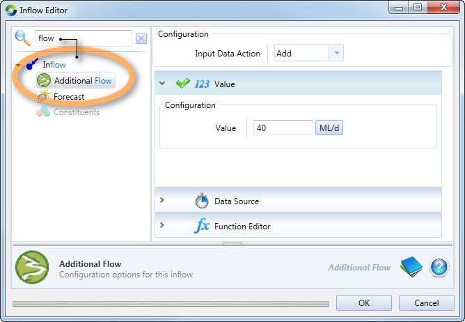
- The ability to search for elements in the hierarchical list, with the result displaying all instances of the query (both parent and child if applicable). Notice that when you enter the search criteria (as shown in Figure 6), the results are displayed in blue. In this case, the term ‘flow’ appears in both the parent and child; and
- When multiple values can be entered for a single parameter, only one value can be adjusted at a time. A highlight (normally blue) indicates the field being manipulated. To edit a different field in this table, click the mouse pointer in the target field.
Figure 6. Inflow node (Search functionality)
Many feature editors support loading parameter information from a file. Where present, the Import... button can be used to load parameters into a feature editor whereas the corresponding Export... button will save the table’s current values to an external file. Additionally, as an alternative to entering or importing discrete parameter settings, the feature editors for many nodes allow for the node’s behaviour to be defined via an arithmetic expression, known in Source as a function (refer to /wiki/spaces/SD411/pages/53282363).
About notes
You can include a text based message associated with a node, link, function, or item in a Resource Assessment System, which can be have a notification level of either:
- Information;
- Warning; or
- An error.
Each of the different message types has a different icon. Figure 7 shows an example of an information note added to an Inflow node.
Figure 7. Notes, Overview
If a note can be added to an item, when you right-click on the item the option Add Note will be available from the context menu, refer to Adding notes to nodes and links. The exception is adding notes to a function, which is done using the Add/Edit Note icon in the Function Editor toolbar, see Adding a note to a function.
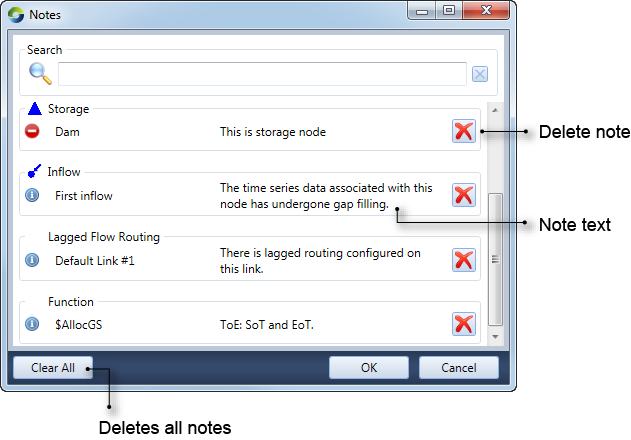
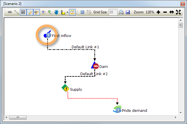
A summary of all the notes configured in a scenario can be viewed using View » Notes. For the example shown in Figure 8, the First inflow and Dam nodes, the $AllocGS function and the Default Link #1 link have notes associated with them.
Figure 8. Notes, Summary
Once a scenario containing notes has been run, the notes are listed in the log reporter with a message type of Note. Also listed is the notification level, the name of the associated item (eg. Inflow 1) and the text message. Furthermore, the Schematic Editor shows all the nodes and links that have notes configured on them. Figure 9 shows two nodes with informational notes, one with a warning note, and one error note.
Figure 9. Schematic Editor, Notes
About piecewise linear editors
Piecewise linear editors are used in a number of places within Source. They allow you to arbitrarily define complex relationships in two dimensions. A typical use is a relationship between inflow (on the X-axis, or abscissa) and outflow (on the Y-axis, or ordinate). As the name suggests, piecewise linear editors are formed by concatenating line segments. The number of coordinate-pairs entered into any piecewise linear editor, and the comparative simplicity or complexity of the resulting relationship "curve", is up to you.
In most cases, piecewise linear editors adhere to the following constraints and conventions:
- The origin is (0,0) and there is no need for extrapolation in the negative direction along the X-axis. If (0,0) is missing from the data set, it may be assumed;
- Interpolation can be used to extrapolate the Y-value for any intermediate X-value;
- The right-most line segment projects linearly to infinity and can be used to extrapolate the Y-value for any X-value along that line. One exception to this rule occurs in the case of BigMod flow routing where the Y-value corresponding with the largest value of X in the table is used for all larger values of X (ie, the data points in the table are treated as though they define the left-hand edge of a histogram bar); and
- Mass balance is respected. For example, losses cannot exceed inflows, so all loss values are clipped to inflows. Similarly, negative volumes are untenable so any projection returning a negative number will also be clipped to zero.
In general, you will avoid problems if you adhere to the following guidelines:
- You should always include an explicit origin of (0,0). This avoids the need for the model to extrapolate in the negative direction along the X-axis. It also avoids any potential problems which might arise if the model silently assumes an origin of (0,0);
- X-values should always be in monotonically increasing order. In the current implementation, an X-value that is entered out of order is highlighted in red until a Y-value is entered, after which Source re-orders the table. You can use this feature to add interstitial coordinates to a table by adding new (X,Y) coordinates to the last row and waiting for the table to re-order;
- Y-values should also increase monotonically. Be cautious if you need to violate this guideline, and especially cautious if the right-most line segment has a negative slope;
- The right-most coordinate pair should lie beyond your most extreme known value. This avoids the need for the model to extrapolate in the positive direction along the X-axis, and also means that you do not need to remember which piecewise linear editors use linear extrapolation of the right-most line segment vs those which project the right-most Y-value to infinity;
- All values should be sensible. For example, there is no point in entering coordinate-pairs that violate mass balance (eg. a loss exceeding inflows); and
- If your model employs optimised ordering, keep your piecewise linear editors to as few data-points as possible. Complex curves usually increase run-time and can sometimes lead to infeasible solutions. Refer to the chapter on Ordering.
Working with date-pickers
Date-pickers are used in a number of places within Source. They are a combination of an editable text field and a pop-up calendar. Figure 10 shows the relationship between the various components.
Figure 10. Date-picker
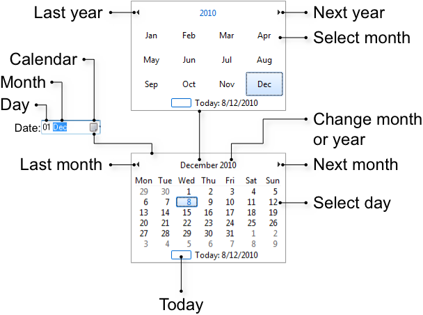
You can edit a date directly by selecting either the Day, Month or Year element within the text field (you cannot select the day of the week). Once an element has been selected, you can also change the selection by using the left and right arrow keys. You can adjust an element’s value by using the up and down arrow keys or by entering a new numeric value. Note that you also use numeric values for the Month element. For example, typing "7" changes the Month element to "July".
Clicking the disclosure arrow at the right of the text field displays a calendar. Within the calendar, you can:
- Change the month, year, decade or century by clicking repeatedly on the current year field;
- Change the month using the Last month and Next month buttons;
- Change the selected date using the arrow keys. The left and right arrow keys adjust the date by one day at a time whereas the up and down arrow keys adjust the date by one week at a time; and
- Select a date by clicking on the day. You can also select "today" by clicking the unnamed button at the lower, left of the calendar.
Selecting a date, pressing return, or clicking outside of the calendar’s confines closes the calendar.
Dockable windows
Many Source windows can be docked within the main window, or arranged independently, depending on your project or scenario requirements. For example, if you have a very large node-link network, you can separate the Schematic Editor panel from the main Source window, thus providing a better view of the entire network. This section explains how to you can customise views of the Source main screen.
The dockable windows include the Geographic, Schematic and Tabular editors, the Map tab, most of the auxiliary windows, and windows belonging to some plugins. The docking and undocking action sticks with a project and scenario when it is saved. If the Schematic Editor is not docked, and a project is saved and closed, when it is re-opened, the Schematic Editor will be in the same position it was when the project was closed. The same applies if Source is closed and re-opened.
Undocking windows
The default position of dockable windows is docked. A single click within the borders of any docked window will activate it. An active window can be identified from either its title bar or from an element within it that is highlighted. For example, the Project Explorer is the active docked window in Figure 1.
Figure 10. Identifying active windows
The windows of some tools may be docked in the main window.
Windows can be reset with View » Reset All Windows.