Note: This is documentation for version 4.11 of Source. For a different version of Source, select the relevant space by using the Spaces menu in the toolbar above
Constituent Sources in Source Catchments Models
Overview
Two new pieces of functionality have been added to the constituents system of Source.
The first extends the granularity at which a user can model constituent generation and filtering. This is achieved by permitting more than one model to be used for generation or filtering on a given functional unit for a given constituent. In the past a user could only define one model for say functional unit ‘FU2’ - constituent ‘TSS’. This is where the idea of ‘constituent sources’ come in. The user can now define multiple constituent sources, for example 'Hill' and 'Gully'. This means they could define a model for FU2 - TSS - Hill and another for FU2 - TSS - Gully. Typically each source would contain both a generation and filter model (like the old system) which would work together, the generation model passing its constituent load to the filter model for filtering with the output from the filter models being summed across all constituent sources for the functional unit.
The second new piece of functionality allows constituent generation / filter models to contain parameters which depend on a parameter from another generation / filter model. The concept is similar to that of functions whereby a parameter can be set from elsewhere in the system. Functions cannot be used here because the function manager is unable to influence the running order of models in a functional unit. So instead the design has a simple parameter linking tool which allows a user to connect one parameter on one constituent model to another parameter on another. The model parameter which is to be written to must have been compiled with metadata indicating that its value should come from another constituent model’s parameter. The function described above is termed as “Define Constituent Model Linkage” in Source, and the linkage procedure and an example are outlined below.
Editing, adding and removing Constituent Sources
The first step when beginning to use constituent sources is to add additional sources to the constituent source list. By default a single source has automatically been added when the scenario was created called “Default”. The screen to add/remove additional sources is found on the “Constituents Configuration” screen, accessed through the main menu “Edit -> Constituents…”.
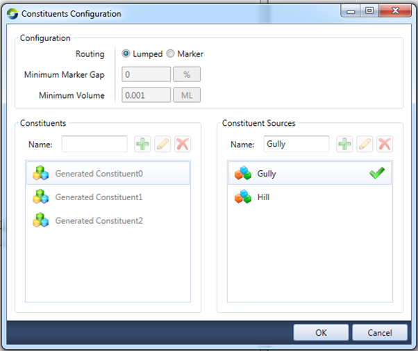
Figure 1. Constituents Configuration screen (Constituent Sources editor on right)
Here we see the constituent sources editor control on the right of the dialog. It shows two sources named “Gully” and “Hill”. “Gully” has a green tick beside it because it is the default source. The source called “default source” without a green tick is not the default source. The default source with the green tick cannot be deleted and it is the source that is automatically used by various editing/configuration tools when no other is specified or where the tool is unaware of constituent sources. Such tools were designed when each FU only had one model per constituent and cannot understand the current design that there is potentially more than one model per constituent, in these cases they are directed to simply edit/configure the default source’s models. The default constituent source can be changed by right clicking on another listed source you want to be the new default and selecting “Set as Default”.
Editing, adding and removing Constituent Sources from Functional Units
Constituent generation and filter models are configured in the “Constituent Model Configuration” dialog access through the main menu “Edit -> Constituent Models…”.
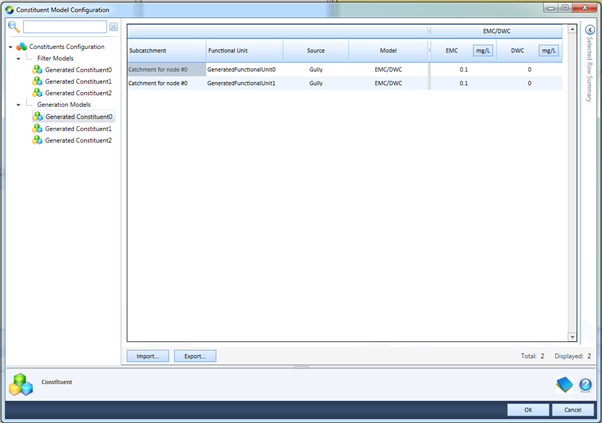
Figure 2. Constituent Model Configuration screen
The screenshot above (Figure 2) shows the constituent generation models for all functional units and constituent sources for the constituent called “Generated Constituent0”. As can be seen in the data grid on the right, the first four columns are; Sub-catchment, Functional Unit, Source and Model. Previously this data grid contained only three primary columns, with the new system having added the column of “Source”. This new column contains cells with a drop down list populated with all of the constituent sources that were defined in Figure 1. This is one method by which the user can edit the constituent source assigned to a model. The remainder of the columns operate as before with the exception of the model linkage column which will be covered later in the document.
The user can to assign the same constituent source more than once for a given FU. However, this operation will be ignored if the same constituent is already existed for the given FU.
To assign a new constituent source to a FU, select the constituent for which you wish to add the constituent source in the tree view on the left and the FUs corresponding row in the data grid on the right. It does not matter whether you are in the generation or filter model data grid, as any additions / removals are automatically applied to both such that every constituent source has a corresponding generation and filter model placeholder.
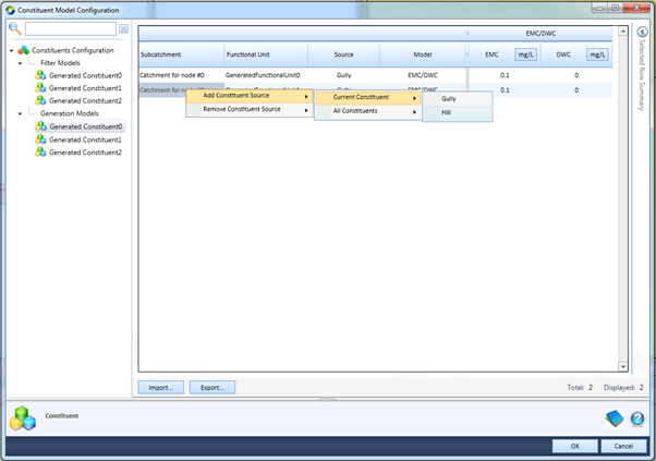
Figure 3. Assigning a new Constituent Source to a Constituent / FU
With the row selected, right click. Select “Add Constituent Source -> Current Constituent -> x” selecting the desired constituent source in place of x (Figure 3). This will add a new row to the data grid allowing the assignment and parameterisation of a new constituent generation or filter model for the selected Constituent / FU (Figure 4).
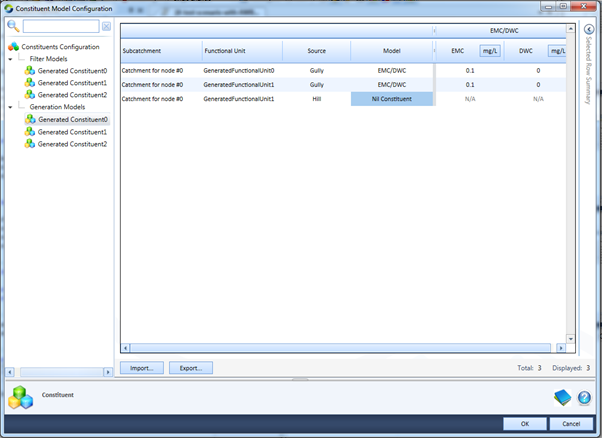
Figure 4. Shows two Constituent Sources for FU1. Gully with an EMC/DWC model and Hill with none
The process to un-assign a constituent source from a FU is almost identical to that of adding one; simply select the row and right click and instead of selecting “Add Constituent Source”, select “Remove Constituent Source” (Figure 3). At least one constituent source must exist at all times, so if the user attempts to remove all sources from a FU, they will all be removed and a new source (the default source) will be automatically added again.
The system also allows for bulk assignments to be made. The user will have noticed that when right clicking on a row and nominating to either Add or Remove a constituent source, two options appear on the next menu. The first (and the one we selected above) is “Current Constituent”. This applies the Add or Remove operation just to the constituent selected on the tree view on the left. The second option is “All Constituents”. This option preforms the “Add” or “Remove” to all constituents regardless of which is selected in the tree view.
Another powerful way of bulk adding or removing constituent sources is to select multiple rows in the data grid which correspond to different FU’s. Selecting multiple FU’s before right clicking performs the selected operation on all of those FU’s in one hit. Selecting all of the desired rows in one go will become more difficult the larger the scenario. To get around this, the user can use the column filtering functionality of the data grid to trim the number of rows down to a more manageable number or they can break the changes down into several smaller changes.
Constituent Model Linking
Constituent generation and filter models may require one or more of their parameters to come from another generation or filter model on each time step. Although rare, these cases do exist and must be dealt with. At the moment only one such model exists in the core framework, the Nutrient Delivery Ratio (NDR) filter model. Each NDR model depends on the input to the Sediment Delivery Ratio (SDR) filter model. For a given functional unit and constituent source, the correct configuration of these filter models would be to assign one SDR to the sediment constituent, and one NDR to each other appropriate constituent. The NDR model has a parameter which it expects will be set to the same value as an input to the SDR. A linkage would then be created between the ‘quick flow in’ parameter on the SDR and the ‘quick flow sediment in’ parameter on the NDRs. The linkage system would, at runtime, ensure that the SDR has run before the NDRs, ensuring the correct flow of data at the right point in time. The system is designed to detect circular dependencies and force the user to remedy their defined linkages before being able to proceed.
The NDR parameter is marked up with a special attribute tag that tells the system to create a custom column in the data grid as shown in Figure 5.
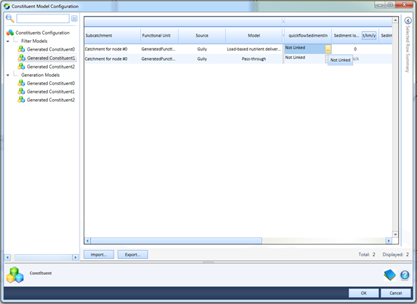
Figure 5. Shows the linkage column “quickflowSedimentIn” for the NDR filter model w/tool tip shown
By default, an undefined linkage show the text “Not Linked”. To link a parameter, click on the “…” ellipsis button in the cell. Doing so launches the “Define Constituent Model Linkage” editor (Figure 6). This editor permits the user to specify where the value which is to be set on the selected parameter comes from. They get to choose a parameter from any model, generation or filter, which exists in the same FU.
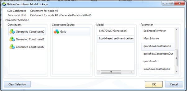
Figure 6. Define Constituent Model Linkage dialog
To make a linkage, the user selects the constituent, constituent source, model and finally the parameter on the model they want to get the value from. If no linkage is required, click the “Clear Selection” button to clear the linkage.
The user may have linked a parameter to another parameter on a model which may get de-selected on the main data grid prior to clicking “OK”. In that case, because the source of the linkage value no longer exists, an error message is presented and the user is unable to proceed until the issue is remedied.
Constituent Model Configuration Import / Export and Copy / Paste
The importing, exporting, copy and paste functionality on the data grids is almost unchanged from the old system. Two important changes were introduced to deal with the constituent sources and model parameter linkages.
When importing into the data grid, the number of rows in the data grid and in the csv file must match prior to importing the csv. This is a hangover from the old system in which the number of rows was much more static and would not typically change. The new system is not yet capable of dynamically varying the number of rows to suit the number of rows in the csv file upon the importation of csv. This issue may be addressed in the future.
When the value of a linkage cell is imported / pasted in, the linkage may not be valid at the time of importation / pasting. An example of this temporary invalidity would be a case where several data grids worth of values (several csv’s) needs to be imported, one after the other. The first csv of a data grid may contain a linkage to a model which does not exist yet because that model type is yet to be imported via the second csv of another data grid. In this case, the linkage is pending validation. It will remain pending until one of two things happen. The first is that the user imports the second csv, creating the expected model type for the linkage to connect too and the situation is resolved. The second is that the user attempts to edit the linkage by clicking the “…” button before the second csv is imported. If this happens the user is presented with a question bar at the top of the Define Constituent Model Linkage dialog. They can choose to keep the pending linkage and close the dialog, or throw away the linkage and define a new one. All pending linkages will be thrown away and revert to “Not Linked” upon the clicking of the “OK” button on the main Constituent Model Configuration screen.