Note: This is documentation for version 4.11 of Source. For a different version of Source, select the relevant space by using the Spaces menu in the toolbar above
Constituents
For introduction to Water Quality in Source, please see Water Quality under fundamental concepts.
Overview of configuring constituents
To configure constituents:
- Enable and define constituents and constituent sources using the Constituent Configuration dialog. See Defining constituents.
- Configure how constituents enter the model. Options are:
- As a point source - see Configuring constituents at nodes.
- Laterally through a link - see Configuring constituents at links.
- Through the surface - see Constituent generation models (for catchment models only)
- Configure how constituents are processed by the model, options are:
- Constituent filters (for catchment models only);
- Storage processing models; and
- Instream processing models.
After you have defined constituents, the Constituent Model Configuration dialog is useful for viewing, selecting and editing:
- the filter and generation models and constituent source(s) for each sub-catchment/functional unit combination;
- the instream processing model for each storage routing link; and
- the storage processing model for each storage node.
See Constituent Model Configuration for more details.
Defining constituents
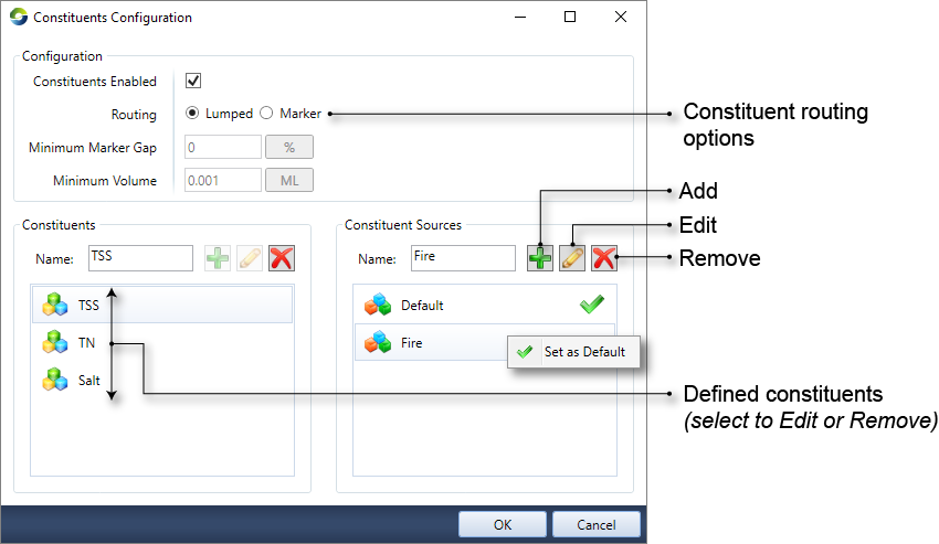
The Constituents Configuration dialog (Figure 1; accessible via Edit ...) is used to enable constituent modelling, and define both constituents and constituent sources:
- You can choose to enable constituents in a scenario using the Constituents Enabled checkbox. Note that disabling constituents results in constituent recorders being disabled as well;
- Specify the type of routing - there are two constituent routing options in Source - Lumped and Marker. Refer to Constituent Routing.
- Define and manage constituents and constituent sources as follows:
- To add a constituent or a source, enter its name in the Name field and click the Add button;
- To change its name, choose it from the list, then enter the new name in the Name field and click the Edit button or
- To remove, choose it from the list, then click the Remove button.
Figure 1. Configure constituents
Constituent routing
There are two types of constituent routing available, Lumped and Marker routing. (Figure 1). Both of these are conservative routing models, which means that they do not change the total mass of constituent in the system.
Lumped routing is the simplest approach, where constituents are routed within a link based on kinematic wave theory. Assuming fully-mixed conditions within a link, the constituent flux and concentration simply move from the top of a link to the downstream end of a link within a time step, preserving the mass balance. Constituent concentrations in a link can be altered by the addition of constituents generated from sub-catchments, external inflows, and losses within a reach; and
- Marker routing considers constituents as particles and tracks their movement within a link, which can be divided into divisions for hydrologic routing purposes. Initially, the model will start with a marker at the end of each division in every link. At every time step, a new marker for each constituent will be created for each division, and the distance a marker moves is driven by the velocity in the division over the current time step. While the flow rate is assumed constant over the timestep, the velocity within the division will change as a result of a change in reach storage. Markers will travel through the river network until they are either merged with adjoining markers or leave the river network (ie. via extractions, decay within the reach, evaporation, groundwater inflows/losses and rainfall). Refer to Marker routing (Particle tracking) - SRG for more information.
For marker routing, you must specify two additional parameters:- Minimum Marker Gap – defines the spacing between markers as either a fraction of the model time-step or fraction of the reach division. This parameter can improve model efficiency by reducing the number of markers that require processing at each model time step. The allowable range is from 0 to 1, with 0 not deleting any markers, while a value of 1 will ensure that at the end of each time-step, there is only one marker defined for each reach division; and
- Minimum volume – volume to maintain constituent mass balance within the links.
Note: When using lumped routing the following applies for storage routing links, storages and weirs that have volumes close to or equal to zero during the run. The working volume is the sum of the initial storage volume and all input flows, minus evaporation. The minimum volume is 0.01 m3, and is not currently user-configurable. When the working volume drops below the minimum volume, constituents are deposited as mass and removed from the system. The deposited mass is recorded in the Deposited Mass parameter (located at Constituents » <constituent name> » Deposited Mass).
Constituent Model Configuration
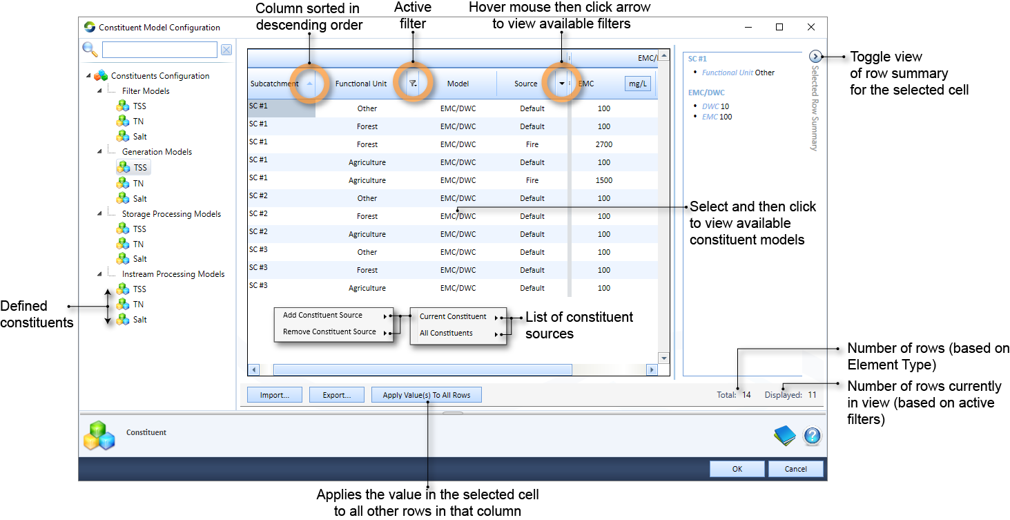
You can assign and manage the constituent generation, filter, instream processing and storage processing models for all constituents in the scenario using the Constituent Model Configuration dialog (Figure 2), which is opened by navigating to Edit ... Before using this dialog, you need to define constituents and constituent sources (as described in Defining constituents) and also either set up your catchment area using the Geographic Wizard for catchments and assigned FU areas and/or add constituents to nodes or links Then, you can use the tree menu on the left to view the filter and generation models for each sub-catchment/FU combination, the instream processing model for each storage routing link, and the storage processing model for each storage node.
The following operations can be undertaken:
- Change the assigned model,
- Change the parameter values or input data for the assigned model,
- Filter columns based on their contents
- Sort columns in ascending or descending order; and
- For filter and generation models you can also change, add or remove constituent sources, see Configuring constituent sources.
Refer to Working with rainfall-runoff models for more details on assigning a model, adding input data and changing parameters. For more information on using filters see Working with filters in the Feature Table. However, there is also a sub-catchment filter to help you find sub-catchments either by name or by using the sub-catchment map, see Sub-catchment filter.
Figure 2. Constituent Model Configuration
Configuring constituents at nodes
In Source, the behaviour of constituents at each node varies. Select Constituents in the node’s feature editor to configure them. Depending on your requirements and the type of node, you can specify either a constituent’s load or concentration at a node. For example, you can only specify a constituent’s concentration on an inflow node.
Inflow node
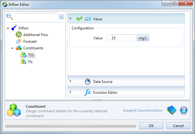
In the node's feature editor, specify the inflow constituent data (as a concentration) using the Constituents item (as shown in Figure 3). This behaviour is similar to flow.
Figure 3. Inflow node (Constituents)
Gauge node
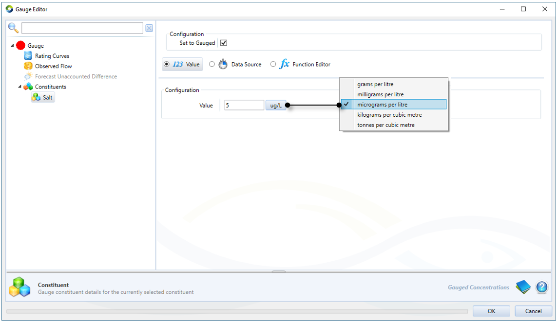
For each constituent, you can specify its observed concentration by entering a value, supplying a time series or defining a function (Figure 4). You can choose to override the modelled constituent concentration with the observed concentration by enabling Set to gauged. Refer to Gauge node - Constituents for more information.
Figure 4. Gauge node, Constituents
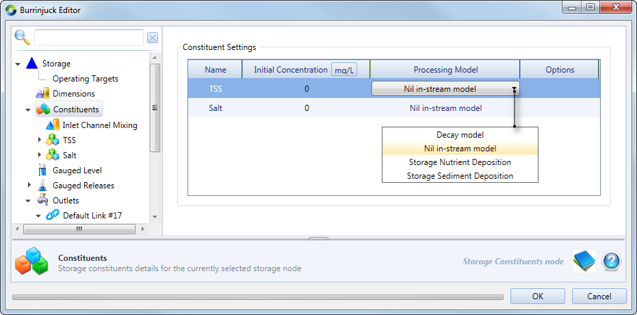
Storage node
For the storage node, you must define the initial concentration of each modelled constituent in the feature editor, under Constituents (Figure 5). You can also change the storage processing model, by clicking the cell with current processing model and selecting the desired model from the drop-down menu (Figure 5).
Figure 5. Storage node, Constituents
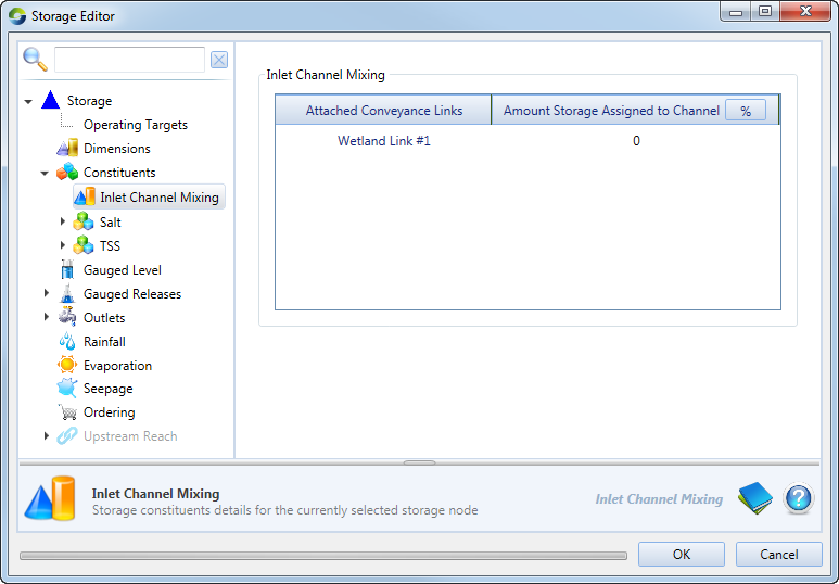
Inlet Channel Mixing allows you to introduce mixing of constituents at a wetland conveyance link (Figure 6). You specify a percentage of the wetland/storage volume that conceptually represents the conveyance link - this is the inlet channel, and the remaining volume represents the main body of the storage/wetland. When water is exchanged between the wetland/river or the wetland/wetland, mixing of constituents is assumed to occur in the inlet channel. If the exchange of water is large enough to flush out the inlet channel, then the constituents will mix with the main body of the wetland, or the river, depending on the direction of water exchange.
Figure 6. Storage node (Inlet channel mixing)
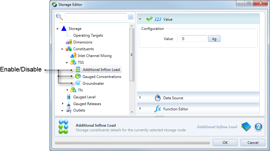
Additionally, for each constituent, you can configure various aspects of its concentration (Figure 7):
- Additional Inflow Load – specify the amount of constituent to be added to the storage per time-step. It is not specific where this constituent mass comes from;
- Groundwater – concentration of constituents entering or leaving the node via groundwater flow. Seepage needs to be configured for the storage, see Storage node - Seepage; and
- Gauged Concentration – the observed concentration at that storage node. This can be used to compare against modelled constituent concentrations. You can choose to override the modelled constituent concentration with the observed concentration by enabling Set to gauged.
Figure 7. Storage node, Constituent concentration
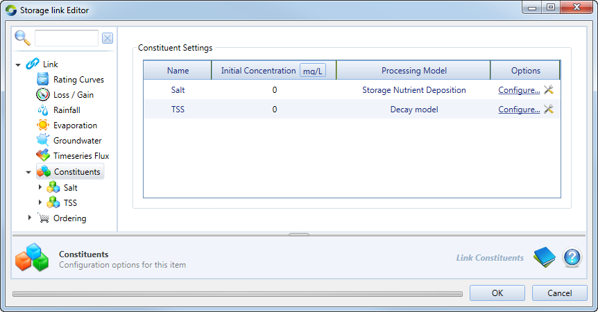
Configuring constituents along links
Constituents can be configured for storage routing links in the feature editor (Figure 7). In this screen, you can specify the link’s constituent concentration when the simulation begins. This parameter assigns a concentration for each modelled constituent in the scenario for the markers created in that link during the model initialisation. You can also specify the instream processing model, the parameters of which can then be configured by selecting Configure…
For each constituent, you can specify an increase in concentration from different sources, similar to constituents in the storage node (Figure 8). The parameters are:
- Additional Inflow Load – specify the amount of constituent mass to be added to the storage routing link per time-step. It is not specific where this constituent mass comes from;
- Groundwater – concentration of the constituent entering the link via groundwater flow; and
- Timeseries Flux – concentration of the constituent entering the storage routing link viaTimeseries Flux.
Note that both Groundwater and TimeseriesFlux need to be configured on the storage routing link for constituents to enter the link using these sources - see Groundwater and Storage routing - Timeseries Flux.
Figure 8. Storage routing link, constituents
Configuring constituent in catchment models
Constituents in a catchment model have a constituent generation model and a constituent filter model for each sub-catchment/functional unit (FU) combination. To configure these, use the Constituent Model Configuration dialog (Figure 2), which is opened by navigating to Edit ... You can configure more than one generation and/or filter model for a sub-catchment/FU combination by using constituent sources.
Constituent generation models
These describe how constituents (eg. sediments or nutrients) are generated within a functional unit and the resulting concentrations or loads passed to the filter model. Click on any constituent to view the associated FU and generation model for each sub-catchment.
Assign and parameterise generation models for a constituent as follows:
- Click on the constituents under Generation Models (in the tree menu).
- Assign a model to the sub-catchment/FU combination:
- Click on the cell in the Model column that you want to change; and
- Click on the drop-down arrow that appears and choose the required model from the menu;
- Assign input data (if relevant) to the model; and
- Parameterise the filter model. Depending on the chosen model, the right-side of the table will populate with the associated default parameters. Click on the cells and edit these values.
The available constituent generation models are:
- EMC/DWC – the Event Mean Concentration (EMC) / Dry Weather Concentration (DWC) model applies two fixed constituent concentrations (EMC & DWC) to an FU to calculate the total constituent load.
- Export rate – this model applies a fixed constituent generation rate to a functional unit (FU) to calculate total constituent load. It requires only a single parameter so is quick to use and therefore useful for exploring sensitivity.
- Nil Constituent – this model is used as a substitute constituent generation model where no constituent load needs to be modelled for a given constituent from a given FU
- Observed concentration – this option allows you to assign observed quick flow and slow flow concentrations.
- Power Function – this model fits a rating curve describing the relationship between constituent concentration or load and discharges. It is a straight power curve, where flow in ML/d has been used to generate a relationship with the solute concentration (mg/L),
- Power Function (flow in mm) – this model is the same as the Power Function model, but uses a normalised power curve, where flow in mm/d has been used to generate a relationship with the solute concentration (mg/L).
The default constituent generation model is Nil Constituent.
Constituent filter models
Filter models represent any transformation of constituents between generation within the FU and arrival at the link upstream of the sub-catchment node. Filter models process constituents within the FU and as with constituent generation models, are applied to FUs. Follow the same steps outlined for generation models to assign, add input data and parameterise constituent filter models.
The available constituent filter models are:
- 1st Order Kinetic Model k-C* – reduces the concentration of constituent leaving an FU as a result of a treatment facility (eg. a grass filter strip).
- Load-based nutrient delivery ratio – reduces the amount of nutrient leaving an FU in the quick flow as a function of the amount of load generated in the FU.
- Load-based sediment delivery ratio – reduces the amount of sediment leaving an FU as a function of the amount of load generated in the FU.
- Pass-through – preserves the amount of constituent generated in an FU and passes this to the downstream sub-catchment node.
- Percentage removal – removes a fixed percentage of the constituent associated with the quick flow of the FU and a fixed percentage of the constituent associated with the baseflow
- RPM filter – The riparian particulate model (RPM) is used to model the trapping of sediment particles in riparian buffers and so reduce the load of sediment and associated constituents to streams. It is intended principally for catchment-scale applications.
The default constituent generation model is Pass-through.
Linking constituent generation or filter models
Note: This functionality is currently under development and not all models can be linked. The description that follows is an illustration of what can be undertaken in Source.
Constituent generation and filter models may require one or more of their parameters to originate from another generation or filter model. The load-based nutrient delivery ratio (NDR) filter model depends on the input of the load-based sediment delivery ratio (SDR) filter model. To configure constituent model linking between these two models for a given sub-catchment/FU combination and constituent source, assign an SDR model to the sediment constituent, and an NDR model to each other appropriate constituent. You then need to define a linkage between the SDR quickflowConstistuentIn parameter and the quickflowSedimentIn parameters of the NDR models. Once the linkage is created, the SDR model is run before the NDR models, allowing the correct flow of data at the right point in time.
To link an NDR model to an SDR model, in the Constituent Model Configuration dialog (Edit ..):
- From the tree menu, under filter model, select the constituent representing sediment
- For the appropriate sub-catchment/FU combinations:
- assign the load-based sediment delivery ratio model, and
- configure the parameters of the model
- From the tree menu, under filter model, select an appropriate constituent (representing nutrients)
- For the same sub-catchment/FU combinations:
- Assign the load-based nutrient delivery ratio model
- For the parameter quickflowSedimentIn click the ellipsis button (...) next to Not Linked to open the Define Constituent Model Linkage dialog.
- Select the sediment constituent from the list of constituents, the constituent source, the Load-based sediment delivery model), and finally the parameter whose value will be used as input (quickflowConstituentIn).
- Click OK to close the dialog.
- Configure the rest of the parameters of the model.
Note: Source detects circular dependencies, and will notify you if a defined link needs to be corrected prior to proceeding.
Constituent sources
Constituent sources allow you to configure more than one constituent generation and/or filter model for a given sub-catchment/FU combination. Each constituent source assigned to a constituent/sub-catchment/FU combination allows you to select different constituent models or model parameters. For each source, the selected generation or filter model and its parameters are applied across the entire area of that sub-catchment/FU. An example use for constituent sources is to model the constituents from a fire in the forest and agriculture functional units of SC #1. First, two sources are defined, Default and Fire (Figure 1). Then the default source is used to model the constituent generation and filtering under natural conditions for both the forest and the agriculture FUs in SC#1. Then the fire source is used to model the additional constituent generation and filtering that results from the fire (Figure 2).
The first step when configuring constituent sources is to add sources to the Constituents Configuration dialog (as described in Defining constituents, Figure 1). There is always at least one constituent source that is the default, it is indicated by a green tick (Figure 1), and cannot be deleted. You can change which source is the default using the Set as Default contextual menu.
For each constituent, every sub-catchment/FU combination is assigned the default constituent source for both constituent generation and constituent filtering. You can change the constituent source from the default or add or remove additional constituent sources in the Constituent Model Configuration dialog (Figure 2), which is opened by navigating to Edit ...
To change a constituent source for a constituent generation or filter model:
- Select the constituent you wish to change the source for (the tree view on the left) under either the filter or generation model (any change to the source is automatically applied to both models for that constituent);
- Select the row with the appropriate sub-catchment/FU combination;
- Right-click and choose Add Constituent Source » Current Constituent » <source name>. This will add a new row to the table, allowing you to assign and parameterise a new constituent generation or filter model for the selected constituent/sub-catchment/FU.
You can also undertake the following actions using the same contextual menu:
- The process to remove a constituent source from an FU is identical to adding one. Choose Remove Constituent Source » Current Constituent » <source name>. Note that at least one constituent source must exist at all times. If all sources have been removed, a new row with the default source will be automatically added;
- Bulk the assignment of a source to multiple constituents can be made using the Add/Remove Constituent Source » All Constituents. This will add that constituent source to that sub-catchment/FU combination for all constituents.
- You can assign the same constituent source to several sub-catchment/FU combination by selecting multiple rows, then right-clicking and choosing the desired constituent source menu item.