Note: This is documentation for version 4.11 of Source. For a different version of Source, select the relevant space by using the Spaces menu in the toolbar above
Representing systems in Source
A Source model is a simplification of the real world, and uses certain conventions to represent important characteristics of the system being simulated. Key features include:
- Flow - rate of water movement past a point per unit time;
- Constituents - is a material that is generated, transported and/or transformed;
- Catchments and sub-catchments - areas that generate runoff and constituent loads;
- Functional Units - areas within a sub-catchment that have similar behaviour in terms of runoff generation and/or nutrient generation. These could be, for example, areas with common land use;
- Nodes - points where flows and nutrients enter the river network, or where some process that is important for modelling, occurs (eg flow measurements at a stream gauge); and
- Links - used to join nodes and to store, route and process flow and constituents.
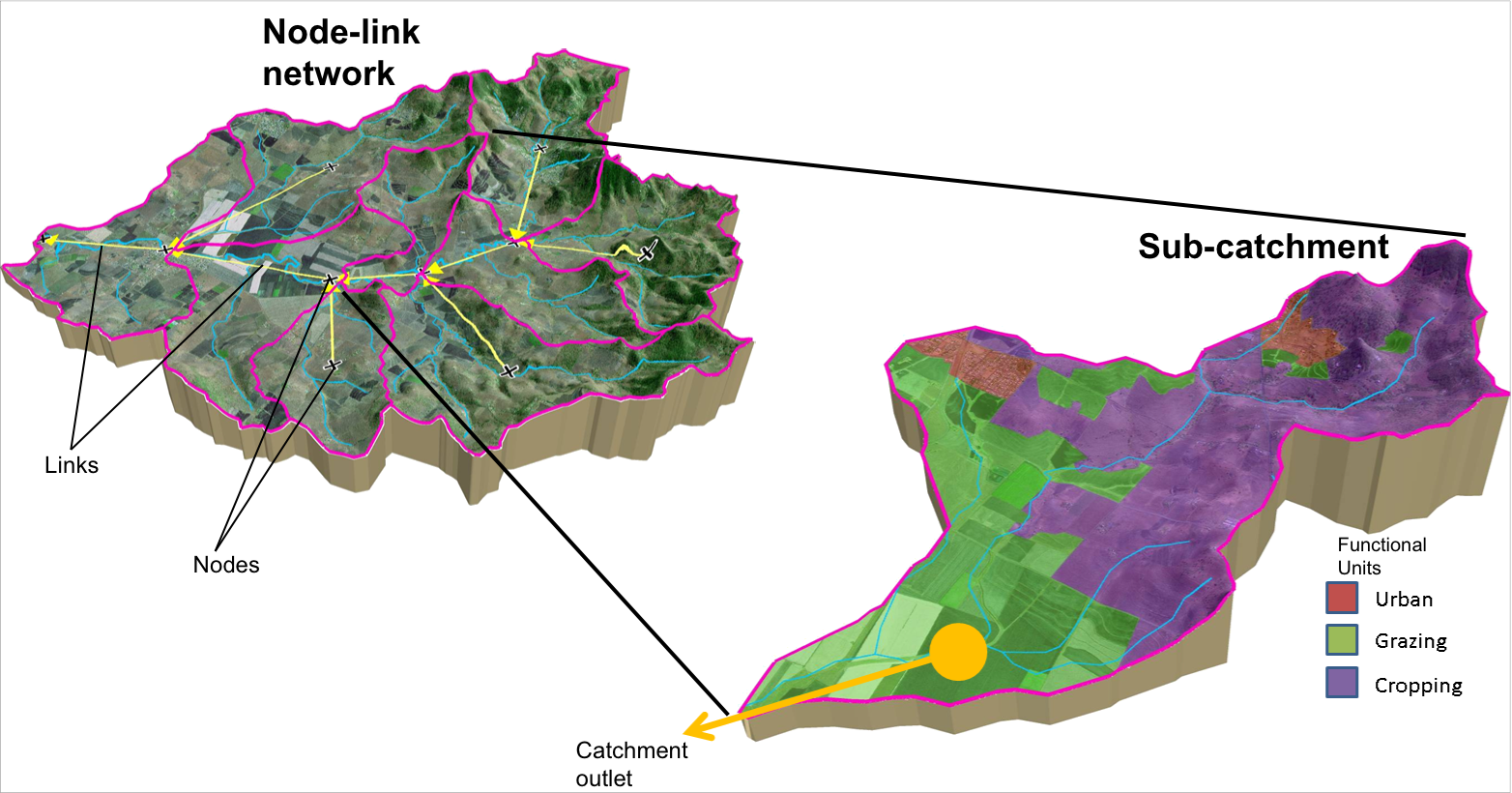
Source uses a node-link style modelling system for generating, transporting and transforming water and constituents within the major channels in a catchment (see Figure 1). Note that not all streams can be modelled, so you must decide which ones are important for a particular application. In urban applications, the basic Source features (nodes, links etc) can be used to create the functionality to model systems such desalination plants andstorm water harvesting applications. Details are provided in the User Guide.
Figure 1. Node-link networks and sub-catchments
Flow
In Source, flow refers to water moving through a node-link network (from sub-catchments, through links to an outlet). Source can be used to predict flow at defined points in a river network, operating down to daily time-steps and reporting at daily to monthly to decadal scales.
Constituents
A constituent is a material that is generated, transported and/or transformed within a catchment. Constituents commonly include sediments, nutrients, contaminants (eg pesticides, heavy metals), pathogens and other water quality properties. Constituent generation models govern the way constituents are generated within a Source model. This may be static or time-varying and could be a function of flow or other variables.
Catchments and sub-catchments
A catchment is the entire area of interest that is being modelled. The first step in modelling is to divide a catchment into sub-catchments. Sub-catchment boundaries can be determined based on stream topography and landforms calculated from a Digital Elevation Model (DEM), or through the analysis of topographic maps.
Catchment analysis is dealt with in detail in the Working with catchments scenarios section and the /wiki/spaces/SD49/pages/54362156. Figure 2 shows an example of a node-link network, which is made up of several sub-catchments.
A selection of sub-catchments will determine the location of the nodes in the node-link model, so sub-catchments need to represent the major sources of water inflows and nutrient inputs. In Source, a sub-catchment is the area flowing into a node. There is no explicit representation of a stream network or surface routing within the sub-catchment.
Functional units
Sub-catchments are divided into areas with a common hydrologic response or behaviour called functional units (FUs), based on various combinations of land use or cover (eg. forest, crop, urban), management, position in landscape (flat, hill slope, and ridge) and/or hazard (however defined). Figure 2 shows an example of this.
Figure 2. Functional units operating in a sub-catchment
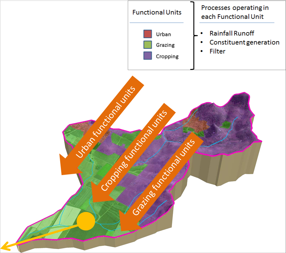
Three basic processes are defined to operate in a functional unit:
- runoff generation - several different rainfall runoff models are available in Source and includeSimhyd, AWBM, and Sacramento. It is also possible to use an observed catchment surface runoff depth;
- constituent generation - produce materials or contaminants such as total suspended solids and total nitrogen; and
- filtering - represents any transformation or storage of constituents that takes place between when they are generated and when they reach a sub-catchment node. It allows representation of physical processes that may occur due to riparian buffers, small dams, detention ponds, or denitrification processes.
Each process is applied as a set of algorithms that deliver the resulting output to the sub-catchment node. The Scientific Reference Guide provides details on the models available for each.
A rainfall runoff model, a constituent generation model and a filter model can be chosen for each functional unit. In some scenarios, the different functional units will use the same component models - for example using the same rainfall runoff model across units but with different parameters that define different runoff attributes (eg.perviousarea). There are also cases where models may need to be different for each functional unit. For example, to represent the differences in rainfall response in an irrigated agricultural field vs a native forest. Similarly, different constituent generation and filter models can be used in different FUs or different sub-catchments. The combination of runoff generation, constituent generation and filtering produces the output for a particular functional unit. In some individual sub-catchments or in some Source applications, only one or two of these processes may be required.
The outputs from all the functional units within a sub-catchment are combined as inputs to the node for that sub-catchment. In this way,output is lumped at the sub-catchment scale.
Source also supports a split of flow and loads into notional surface (quick) and subsurface (slow) portions from each FU.
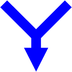
Nodes
Nodes represent places where actions or measurements occur in a river system. For example water can be added, extracted, stored, recorded, or have a change in ownership. A node can be used to represent things that actually happen over a large physical area but which, for modelling purposes, occur at a single point, such as inflows from a catchment, or extractions from a group of off-takes. In sub-catchments, they provide a position in the catchment network where water management information, such as extractions and demands, can be placed. In Source, nodes are depicted using the icons shown in Figure 3.
Figure 3. Node icons for Source

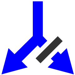


Links
Links represent river reaches but there are some important differences. A reach refers to a physical section of a river, while a link is a logical connection within a Source model. A link will sometimes be defined as having zero length (to conveniently represent certain processes), which is not possible for a reach. Links act to store water and route or process water and constituents passing between nodes (Figure 4). You can only connect nodes using links. You cannot connect two links to each other without an intervening node. Links also allow modelling of interaction with the floodplain.
Figure 4. Connecting nodes with links
![]()
In Source, links are depicted as lines with arrowheads indicating the direction of flow. Links allow modelling of several basic ‘processes’. Refer to this link for the different types of links available.