Note: This is documentation for version 4.11 of Source. For a different version of Source, select the relevant space by using the Spaces menu in the toolbar above
Scenario Transfer Node
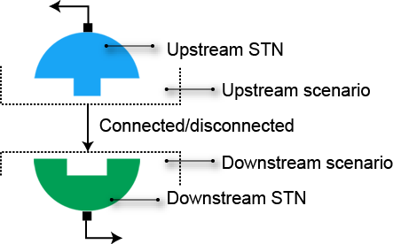
The Scenario transfer node (STN) handles the joining of two scenarios and conceptually comprises of two components, the Upstream STN and Downstream STN (as shown in Figure 1). The node links two scenarios and runs them together. Constituents, orders and ownership are passed between the two scenarios. However, off allocation does not operate over scenarios, instead, the STN operates like an off allocation boundary - similar to the Transfer Ownership node.
The STN operates in either a connected or disconnected mode:
- In connected mode, the Upstream STN passes information such as flow and constraints to the Downstream STN, while the downstream STN passes information such as orders to the Upstream STN. This links the two scenarios together; and
- In disconnected mode, the scenarios run independently of each other. The Upstream STN acts like a minimum flow requirement node and the Downstream STN acts like an inflow node.
See Running Linked Analysis for more information.
Figure 1. Scenario Transfer node
Adding STNs
Connecting two scenarios with an STN requires adding both an Upstream STN and a Downstream STN. Ensure both upstream and downstream scenarios are in the same project (see Importing Scenarios).
In the upstream scenario, you add the STN to an outlet of the model. In the downstream scenario, you add the STN to an inlet of the model. In a schematic scenario, you can add an STN and connect it with a straight through link to an inlet or outlet, as appropriate. In a catchment scenario you can also change the node model of an existing node at an outlet or inlet. When linked to the network, the STN node icon will automatically change to an Upstream or Downstream STN, depending on whether the connection is downstream
Configuring STNs
Connecting STNs
To connect an Upstream STN to a Downstream STN:
- Open the feature editor of one of the STNs (eg. Downstream STN) and select Scenario Transfer (Figure 2)
- Select the desired scenario as the Scenario Target from the list of all other scenarios in the project (eg. Upstream Scenario, Figure 2).
- Select the name of the STN that you wish to connect to as the Node Target (eg. Upstream STN, Figure 2)
Once you have connected an STN using its feature editor, the other STN's feature editor updates with the corresponding Scenario Target and Node Target. If you Clear the connection in either STN feature editor, it will also be deleted from the other STN.
Figure 2. STN, Connecting Scenarios
![]()
Configuring disconnected modes
An Upstream STN acts as a minimum flow requirement node in disconnected mode. If desired, configure the minimum flow requirements by opening the Upstream STN feature editor and navigating to Scenario Transfer » Disconnected » Minimum Flow Requirement, see Minimum Flow Requirement node.
A Downstream STN acts as an inflow node. If desired, configure the inflow by opening the STN feature editor and navigating to Scenario Transfer » Disconnected » Inflow, see Inflow node.
For both Upstream and Downstream STNs, you can configure ownership and constituents in disconnected mode.
Constituents
Once constituents are defined in both the upstream and downstream scenarios, you can map constituents between the two scenarios using the Downstream STN feature editor. Choose Scenario Transfer » Connected » Constituent Mapping and click Add (as shown in Figure 3).
Figure 3. STN, Constituent mapping
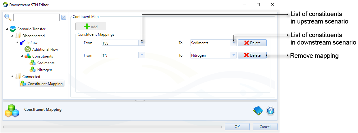
A model will operate even if the constituent processing methodology (lumped or marker) is different for each scenario. For example, consider the upstream scenario is configured with lumped routing and the downstream scenario with marker routing. Constituents will be passed from the Upstream STN to the Downstream STN even though the methodology is not the same.
Ownership
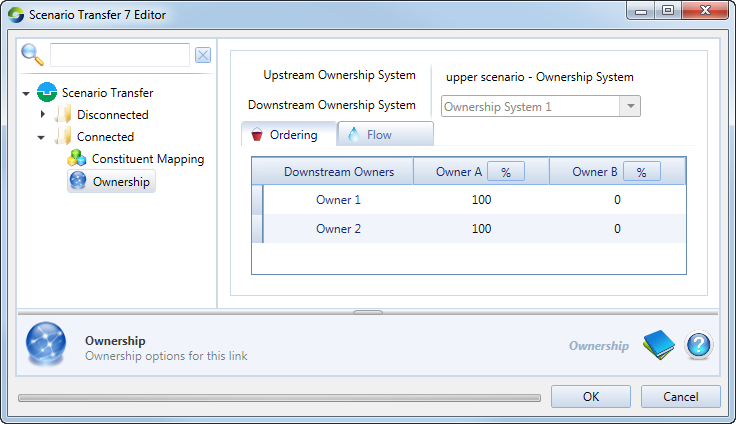
When linking scenarios with ownership systems, an STN acts as a boundary node. Ownership can be set up in the Downstream STN feature editor using Scenario Transfer » Connected » Ownership (as shown in Figure 4). Configuration of ownership is similar to the Transfer Ownership node (when set up as a boundary node), see Transfer Ownership node.
Figure 4. STN, Ownership
Running linked analysis
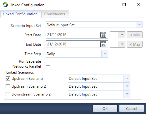
To run scenarios linked by STNs first make one of the scenarios the active scenario. Select Linked Analysis from the Simulation toolbar, and then click Configure to open the Linked Configuration dialog (Figure 5). Under Linked Scenarios is a list of all other scenarios in the project. To run the scenarios in connected mode, enable the linked scenario(s) from this list (eg. Upstream Scenario, Figure 5). To run the active scenario in disconnected mode, leave all scenarios in the Linked Scenarios list disabled. Note, if you enable a scenario that is not linked to the active scenario via an STN, when you run the model the scenarios will both be run, but they will run independently of each other.
Figure 5. Linked Analysis, Configuration
![]()