Note: This is documentation for version 4.11 of Source. For a different version of Source, select the relevant space by using the Spaces menu in the toolbar above
Water user node SRG
Overview
Description and rationale
In any river system, water users require water for a range of purposes including;
- irrigating crops,
- urban, industrial and rural stock and domestic use, and
- managing environmental water entitlements, which may or may not result in an extraction from the river.
The Water User node provides functionality needed in Source to be able to model water use. The functions performed by the Water User node include managing orders and extractions (either with or without an accounting system), setting priorities to determine the sources used for extraction and directing the return of surplus water to rivers, groundwater (by infiltration) and water user storages.
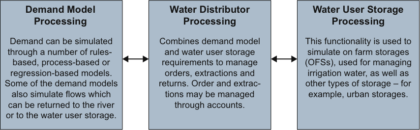
A water user is modelled as comprising three components: a water distributor, a demand model and (in some cases) one or more water user storage units. Of these, the water distributor and the water user storage components are integral parts of the Water User node but the demand model is separate. These three components exchange information as illustrated in Figure 1.
The water distributor component manages orders, extractions and returns. It manages the distribution and carries out its function through an exchange of information with the other two components;
The demand model can be chosen by the modeller from one of the options available in Source. Alternatively, new demand models can be developed and linked to the water distributor using the ‘plug-in’ concept.
The water user storage component is used to simulate an off-river storage associated with a given water user. It can represent;
- an on-farm storage (OFS) used for irrigation;
- an off-river storage used for urban demands; or
- an off-river storage used to meet environmental demands.
Figure 1. Water user model components
At least one Supply Point node is also required to determine where water is to be extracted. Extractions may be from a regulated river, from an unregulated river or from groundwater. The Supply Point node is also used to specify a number of other factors, including delivery efficiency, travel time, pumping capacity and the flow rate above which overbank flows occur. More details are available in the Supply point node - SRG entry.
The Water User node provides the same input to both the rules-based and optimisation-based ordering schemes available in Source. Consequently, in the model run sequence, the processing associated with the water user occurs before the ordering phase starts.
Contents
Structure and processes
The processing carried out by the water user is best described by considering it as a system comprising of three components: the water distributor, the associated demand and any associated water user storage units. During each of the three model execution phases — initialisation, ordering and flow — processing is mediated by a set of interactions between these three components.
The interactions between the three components are summarised in the flowcharts in Figure 2 (order phase) and Figure 3 (flow phase).
The following is a high-level description of the information passed between these three components:
- Demand model: Tells the water distributor the volume of water required. Also passes any excess water to the water distributor model.
- Water user storage: (Commonly referred to as the ‘on farm storage’ (OFS), but includes other storage types.) Tells the water distributor how much water is available in the water user storage for the demand model to use. Also tells the water distributor whether orders should be placed to top up the water user storage. Spills from the water user storage are also passed to the water distributor.
- Water distributor: Tells the demand model and water user storage model how much water is already planned for extraction at future time steps, how much water is available at the current time step to meet requirements and the maximum that may be ordered (based on accounts and volume in water user storage).
The next two sections elaborate on the steps that make up the order phase and the flow phase, respectively. For further information, refer to the Additional functions section.
Ordering phase
Figure 2 depicts the processing for the ordering phase and the flows of information used to support this processing.
Figure 2. Process flowchart – order phase
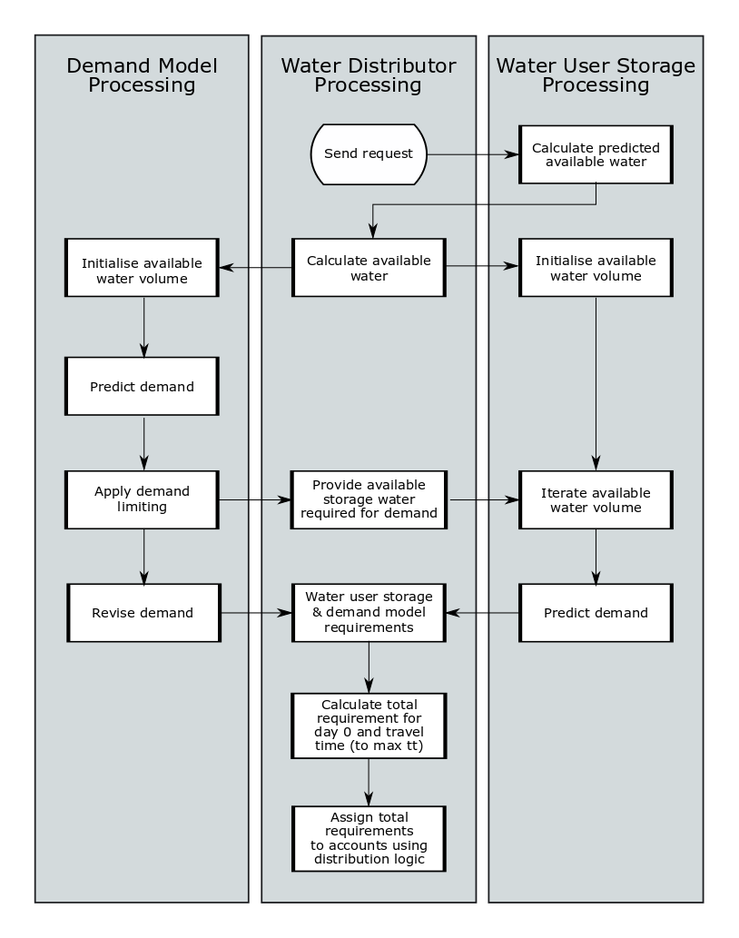
In more detail, the key steps in this process are:
- Calculate predicted water availability (water user storage). The water user storage passes to the water distributor a prediction of the amount that it expects to be storing, allowing the water distributor to estimate the amount it can call on the water user storage to supply. The prediction by the water user storage takes into account expected inflows and outflows, including the following:
- Inflow: regulated orders in transit and expected to be met
- Inflow: opportunistic requests expected to be met (e.g. an allocation made by an off-allocation flow-sharing node)
- Outflow: expected extractions from the water user storage for the demand model
- Outflow: open water surface evaporation and seepage predicted based on the user-specified values in the water distributor “forecasted net evaporation” table [Note that the averages from time series data are not used where no forecast data are entered.]
- Outflow: expected seepage from the water user storage.
If the predicted storage volume is less than the required reserve, an order is placed to meet the shortfall.
- Initialise water volume. The water distributor calculates the water available from upstream dams and water in stream. It determines from the water user storage a prediction of the amount it expects to be storing, allowing the water distributor to estimate the amount it can call on. The water user storage can supply water to the water distributor up to an amount that would require it to deplete the user-specified required reserve (for details, see Maintaining required reserves).
- Predict demand (demand model). In a regulated river system the demand model specifies a regulated requirement. In the case of crop models, an opportunistic requirement may also be specified.
- A regulated requirement results in a release from an upstream storage, if possible, when needed to meet the water user’s order. This may not be needed if forecast inflows between the storage and the water user are sufficient (see Inflow Node section) or if the water user storage is specified as the first priority for water supply and sufficient storage water is available.
- Opportunistic requirements do not result in storage releases. An opportunistic request may be placed to an upstream off-allocation flow-sharing node (see Off-allocation Node Section). This is not an order to release water; rather it is a request for access to opportunistic water. In the flow phase, it could be met from a number of sources of water: overbank flow, which is not subject to accounting rules; pumped off-allocation water where access has been granted by the off-allocation flow-sharing node; or rainfall. See IQQM Crop Model SRG for further detail about the IQQM crop model opportunistic requirement. The water user storage can also generate an opportunistic requirement (refer to Simulating filling above the reserve).
Where water is not delivered within the time step, regulated orders must be placed in advance of the time at which the extraction is required, to allow an upstream storage to release the water in time.
In an unregulated system there are no orders and therefore no need to forecast demands. A water distributor in an unregulated system can have its water requirements met if there is sufficient flow above the thresholds specified at the supply node. Extractions can be limited through usage limits on accounts.
- Provide water from storage required for demand. The predicted demand is constrained by demand limits and the constrained demand is calculated. The amount of water available in the water user storage to supply the demand is extracted and the water user storage volume adjusted.
- Water user storage and demand model requirements. Demands from both the demand model and water user storage are combined to calculate total requirements. The individual demands are calculated as follows:
- For the water user storage, the adjusted storage volume is used to calculate the water required to bring the storage up to the target volume. Demands are generated for this amount of water.
- For the demand model, the remaining demands after applying demand limiting constraints, and supplying the water available from the water user storage are calculated.
- Calculate travel time requirements. Because the water used to fill orders may need to travel for a number of days, it is often necessary to plan ahead in placing an order. This means that the model needs to incorporate ways to predict demand, as well as allowing for circumstances, such as unexpected rainfall, that cause users to need to change their orders.
Where water is not delivered within the time step, regulated orders must be placed in advance of the time at which the extraction is required, to allow upstream storage to release water in time.
Opportunistic requests must be placed in advance if a travel time is specified between the off-allocation flow-sharing node and the water user. This may occur where a flow-sharing node manages a number of water users in a large river system (i.e. there is a travel time between water users). A decision about how to share the opportunistic water is then needed before the first water user extracts it, which means that a forecast of all opportunistic requirements is required.
The maximum delivery time for a water user is determined as follows:- For regulated orders it is the lag between the most upstream supply storage to which the water user may send orders and the furthest downstream supply point associated with the water user. The travel time is configured in the Supply Point node by the modeller.
- For opportunistic requests it is the lag between the off-allocation flow-sharing node and the furthest downstream supply point associated with the water user.
- Assign total requirements to accounts. A water user may have one or more accounts in a resource assessment system. In a regulated system these accounts may relate to either regulated water or opportunistic water. Where the water user has multiple accounts of a regulated type, orders are distributed to these accounts through a set of distribution rules. Refer to Distribution for details of these distribution rules. The modeller needs to specify priorities for access to water if the water user:
- is connected to more than one supply point, or
- has multiple accounts through which orders can be placed (note that a water user storage is represented as an account).
Flow phase
Figure 3 depicts the processing associated with the Flow phase.
Figure 3. Process flowchart – flow phase
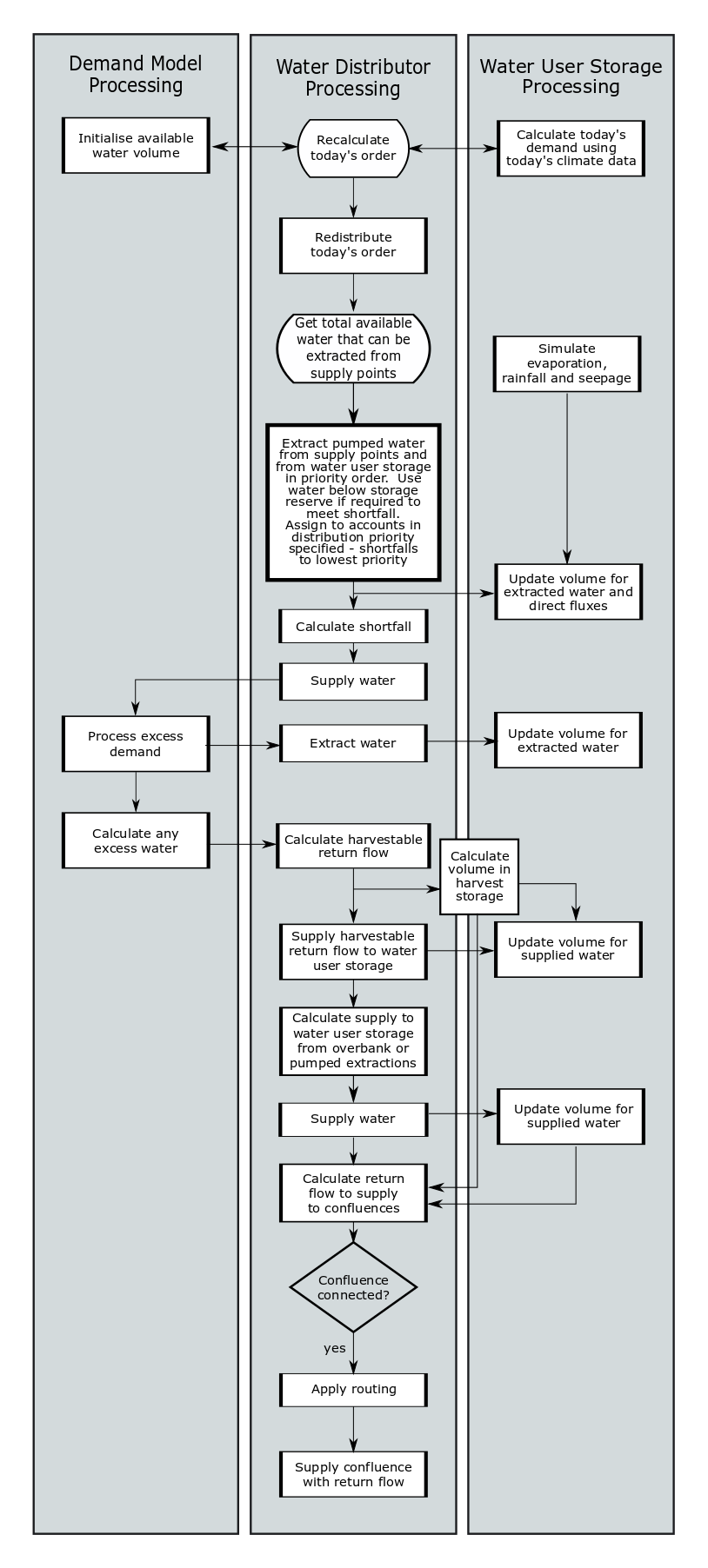
The following are some of the key steps in this process:
- Recalculate todays order. Using today’s climate data for both the water user storage and the demand model. For some demand models, the ‘forecast’ demand is the same as the final demand. However, others can provide an updated estimate at this stage.
Redistribute the orders to the water user storage and the supply points according to distribution logic. - Calculate total water availability.
- Obtain updated volume and level from the water user storage. The volume available in the water user storage for the water distributor is calculated after rainfall, evaporation and seepage have been simulated but before any other inflows/fluxes to the water user storage are processed. In addition to using available water to meet orders it has received, the water user storage can be used to make up for shortfalls in meeting the demand model’s water requirements (including both regulated and opportunistic requirements). Shortfalls can be extracted from any volume in the water user storage above the dead storage; this means that the water user storage volume can drop below the reserve volume in order to meet a shortfall.
In account-based distribution the water user storage functions like an account. The modeller can configure the priority for extracting water from the water user storage alongside the priorities configured for other accounts. However, the modeller cannot configure a priority for filling the water user storage above the demand model. Water extracted to supply the water distributor will always be supplied to meet the demand model demand prior to meeting any water user storage demand. This means the water user storage will only be refilled when there is excess water after supplying all the demand model requirements.
- Extract water. The water distributor combines the volumes required by the demand model and the water user storage to determine how much water to extract at the supply nodes and how much to extract from the water user storage.
In certain cases the volume extracted differs from what was originally ordered:- Where the final calculation of demand is different from what was forecasted. If the final requirement is less than the amount ordered, then less is taken, except in the case of order debit accounts where the extra water is taken if it can be stored in the water user storage. If the final requirement is greater than what was ordered, then the additional volume can be taken if overbank water is available. Alternatively, excess demand model requirements can be met from a water user storage, if sufficient active storage volume is available.
- There is a delivery constraint (e.g. due to storage release capacity or maximum flow node). In this case a reduced volume will be extracted based on the restriction rate.
Two types of extraction can occur at the Supply Point:
- A ‘pumped extraction’, limited to the pumping capacity specified for the supply point. The specified ‘pumping capacity’ may actually relate to a channel capacity rather than a pump capacity.
- Overbank harvesting subject to an overbank flow threshold. Any volume above the overbank flow threshold is assumed to be available (i.e. not subject to the supply point’s pumping restrictions). However, transferring the overbank volume into a water user storage is still limited by the water user storage pumping capacity.
In a Use Debit system, overbank harvesting allows the water distributor to reject the ordered water and extract water without incurring an account debit. This also applies to opportunistic requests; if the order can be met through overbank flow then this volume is not counted as part of an off-allocation usage limit. Order Debit accounts cannot use overbank water to avoid incurring a debt as the account is debited when the order is placed.
A supply point takes the total volume required by the water distributor at this time step, if possible; otherwise it takes what it physically can take (limited by the available water and pumping capacity). Similarly, extractions from the water user storage are limited to what is physically possible and the volume required by the water distributor. The physical constraint on extractions from the water user storage is the available volume in the water user storage above dead storage. Extractions from the water user storage are not subject to the water user storage pump capacity constraint.
A supply hierarchy is used to distribute pumped and overbank extractions and to determine extractions required from the water user storage. The hierarchy determines how shortfalls in supply are managed and also how overbank flow is assigned to accounts.
At each step extractions are limited to the following:
- Volume available for extraction
- For controlled extractions, the remaining available pumping capacity.
- Volume of the requirement which has not been met.
If there is a mixture of order and Use Debit accounts and less is taken than is ordered, the method in which the extractions are assigned to accounts depends on whether there was a shortfall or order rejection:
- In the case of a shortfall, extractions are assigned to accounts using the order phase distribution rules. This means that the shortfall will be assigned to accounts starting with the lowest priority account. Any shortfall in supplying order debit orders will result in a re-crediting of that account balance.
- In the case of an order rejection, the reduction in volume will be associated with the Use Debit account if possible. See Figure 4 for more detail. Order rejection is processed prior to shortfalls.
- Calculate shortfall. The volume in the water user storage is updated including any extractions and direct fluxes, and then the shortfall is calculated.
- Supply water. The water is supplied to the demand model.
- Process excess demand. If demand is not met by all of the sources of supply in the first phase of computation, the shortfall is recalculated and the water user storage is called upon to supply what it can. This is done because the estimates of water availability may be inaccurate when the water user first processes its orders. During the flow phase computation, the nodes in the network are generally executed from upstream to downstream. When a supply point is encountered, the attached water user is executed with an initial estimate of what is available at all supply points. Then the first supply point and the nodes in the rest of the network are executed. The water user is then executed again with the actual current day available water from all of the supply points.
- Calculate excess water. Excess water can be generated by rainfall exceeding the capacity of the soil profile to store water, causing runoff. Also irrigation water applied may generate runoff if configured to do so in the crop model. A portion of the runoff or applied water may return, either being directed to the water user storage or back to the river.
- Calculate and supply harvestable return flow to water user storage. If a water user storage exists and the water user storage parameter Harvestable Return Flow is greater than zero then water can be returned to the storage. The Harvestable Return Flow parameter defines the percentage of the return flow that can be sent to the water user storage. The storage model may further limit the volume of return flow to water user storage based on available airspace in the water user storage and available water user storage pumping capacity (see Storing on-farm runoff).
- Process harvest storage. If the water user also has a harvest storage water will be directed to that storage first. In the current timestep, the existing volume in the harvest storage is directed to the storage. This volume can be reduced at a rate either set by the harvest storage pump capacity or, if there is no harvest storage pump, by the water user storage pump capacity in combination other water being pumped to the storage on that day. When the water is pumped out, the harvest storage receives the harvestable return flow and calculates if there is any spill. Spill is directed straight to the downstream link to return to the river at a confluence if there is one. The remainder of the water stays in the harvest storage until the next timestep.
- Supply water. If there is no harvest storage, the return flow supplies straight to the water user storage. Also the opportunistic water or planned extractions are supplied to the storage. If there is spill, it returns to the downstream link.
- Calculate return flow.
- Apply routing. If there is a downstream link, linear storage routing may be applied as configured in the Return Flow tab at the water user.
- Confluence node.
- If a confluence node is connected to a water user node, the return flow that has not been delivered to the storage can be returned to the river. Any spills from the storage will also be returned to the river.
- If a confluence node is not connected to the water user node, water user storage spills and demand model returns that are not sent to the water user storage will both be considered as losses.
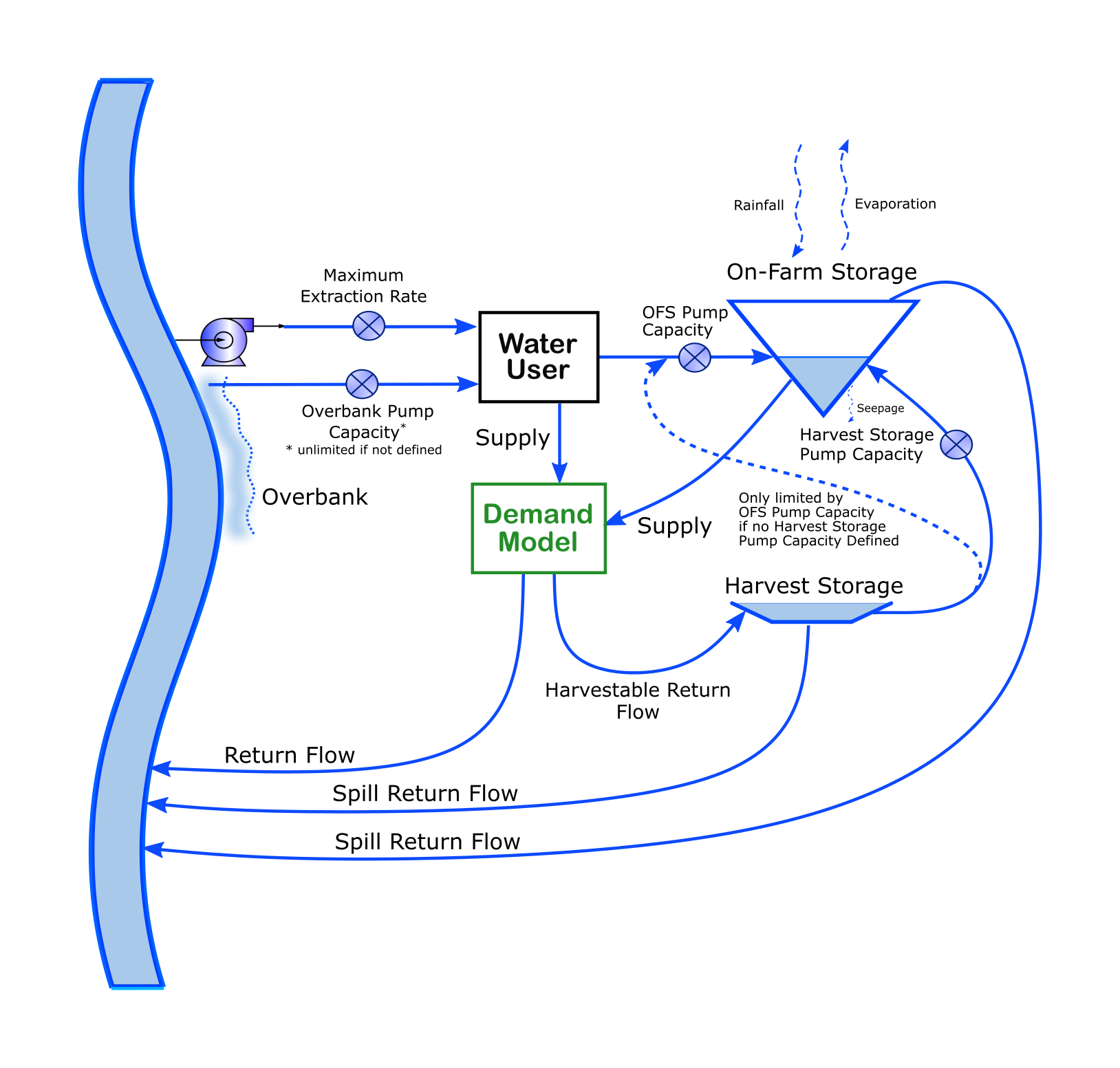
Diagramatic Overview
An overall simplified illustration of the flow paths for a water user are shown in Figure 4. This includes the supply from the river, the on-farm storage and return flows. Note that this is a simplified example, as there may be multiple supply points and also multiple on-farm storages.
Figure 4. Water User flow paths including Supply Point, On-farm Storage and return flow
Additional functions
This section provides more detail on the operation of the three components that make up the water user. Less detail is provided for the demand model, as there are a number of types of demand models, which are described in the following pages;
- Time series demand model - SRG,
- Monthly pattern demand model SRG,
- Pride Demand model - SRG,
- IQQM Crop Model SRG, and
- Irrigator Demand Model - SRG.
Water Distributor / Account Holder
The water distributor allows the modeller to set priorities on where to source water from and place orders to.
Account Sharing Distribution Method
When resource assessment and accounting are configured for the system, the orders and extractions for the water user are managed through the water user’s accounts (see the Resource Assessment chapter).
A water user may have one or more accounts in a resource assessment system. In a regulated system these accounts may relate to either regulated water or opportunistic water. Where the water user has multiple accounts of a regulated type, orders are distributed to these accounts through a set of distribution rules.
Distribution rules use two key concepts: the priority order and the share ratio. The priority order specifies which accounts should be used first, if possible. If a number of accounts have the same priority order, the share ratio is used to define how to distribute orders between them. If all accounts at the first priority level are completely used, then the distribution of orders continues using the next priority level accounts. An account is completely used if either there is no water in its account or if the pumping capacity at its associated supply points has been fully used.
Starting with the first priority level, the following steps further detail the distribution methodology:
- For all accounts at the current priority level, calculate the relative share to be assigned to each account. The relative share is the user-defined share for the account divided by the total for all accounts at this priority level. The total for all accounts ignores accounts that have no available water or no available extraction capacity at the required time step.
- Assign the order to accounts based on the relative share ratio subject to delivery time constraints, remaining extraction capacity and available water in the account.
- If the order has not been fully distributed and any accounts at this priority level have remaining available water and extraction capacity, then repeat steps 1 and 2.
- If all accounts at this priority level are completely used, then move to the next priority level and repeat steps 1 to 3.
If an account is linked to multiple supply points, then the order is distributed between them in equal proportions, if possible. If one or more of the account’s supply points no longer have pump capacity, the account distributes the order proportionally between the others.
If there are multiple accounts and more than one uses a supply point, then the highest priority account has full access to the supply point pumping capacity before any lower level accounts.
If the water user storage requires water, it generates an order. The distribution of the water user storage order to accounts ignores the water user storage account. Apart from this, the distribution of the water user storage order uses the same logic as above. The water user storage can generate regulated orders, which will be distributed to the regulated accounts. It can also generate opportunistic requests, which are assigned to the opportunistic account.
Non-Account Sharing Distribution Method
The distribution logic for the non-account sharing option defines how, ideally, orders are distributed to supply points. However, if any of the supply nodes is unavailable, a redistribution occurs. In this case the relative share assigned to each supply point is recalculated by ignoring the supply points with no remaining capacity.
Reporting water availability and the status of accounts
When the Account Sharing Distribution Method is used, the water distributor can only place an order up to the remaining volume in its account/s.
For Use Debit accounts, the volume remaining in its accounts needs to be predicted. This is because, for systems with non-zero travel time, an account may already have an order in transit that it may extract. As the Use Debit account is only debited once the extraction takes place the current account balance does not reflect the balance that will be available at the time step for which a new order is being placed. The predicted account balance is equal to the current account balance minus any planned extractions (i.e. existing orders).
If a water user storage has been configured, the total available water to the demand model is assumed to be the remaining volume in accounts plus the predicted available volume in the water user storage.
When the Non-Account Sharing Distribution Method is used, the available volume is assumed to be unlimited. If there are physical constraints at any of the storages, the water distributor does not know about them during the ordering phase.
Supply hierarchy
A supply hierarchy is used, as described below, to distribute pumped and overbank extractions and to determine extractions required from the water user storage. The hierarchy determines how shortfalls in supply are managed and also how overbank flow is assigned to accounts.
- Overbank flow is used to meet the following requirements in the specified sequence:
a) Demand model requirements in excess of the orders placed
b) Regulated orders placed by Use Debit accounts. If there are multiple such accounts the overbank flow is assigned to the accounts in the reverse order in which orders were distributed (i.e. use overbank flow to remove the need to extract from the lowest priority account type first)
c) Opportunistic requirement including any opportunistic requests placed.
- Pumped extraction is used to meet the following requirements in the specified sequence:
a) Regulated requirement in the priority order specified in the distribution logic
b) Opportunistic requirement
- Extraction from the water user storage is used to meet remaining demand model requirements. The water user storage can be emptied below the reserve, down to the dead storage, if required to meet the demand model requirements (note that this includes meeting IQQM crop model opportunistic requirements).
Assigning return flows from the demand model
The demand model may return water to the water distributor to simulate, for example, rainfall runoff and irrigation runoff. The water distributor determines how the return water should be distributed:
- If a water user storage exists and the water user storage parameter Harvestable Return Flow is greater than zero then water can be returned to the storage. The Harvestable Return Flow parameter defines the percentage of the return flow that can be sent to the water user storage. The storage model may further limit the volume of return flow to the water user storage based on the available airspace in the water user storage and the available water user storage pumping capacity (see Storing on-farm runoff).
- If the water user node is connected to a confluence node the return flow which has not been delivered to the storage can be returned to the river. Any spills from the storage will also be returned to the river.
- If the water user node is not connected to a confluence node, then water user storage spills, and demand model returns not assigned to the water user storage, will both be considered as losses.
Water User Storage
Simulating rainfall, evaporation and seepage
Rainfall, evaporation and seepage are each calculated as a depth applied to the surface area of the water in storage. If a volume–area relationship has been specified, the surface area is calculated based on volume in storage at the end of the previous time step.
Storing on-farm runoff
Irrigation return water and rainfall runoff can be pumped into the water user storage. These processes are explicitly modelled only by IQQM crop model 2. However, other demand models also include return flow functionality. The percentage of the return flows that can be passed to the water user storage is defined through the harvestable return flow parameter in the water user storage GUI. The water user storage can be filled up to the storage capacity with return flow. Any excess water is returned to the water distributor as a spilled volume. If the water user is connected to a confluence node, then the spilled water is returned to the river; otherwise it is considered a loss.
The rate at which return flow can be passed to the water user storage is limited by the water user storage pumping capacity. And if there is a harvest storage, the return flows pumped to the water user storage are limited by the harvest storage pump capacity. Pumping return flow has priority over pumping other water sources into the water user storage.
Maintaining required reserves
The modeller can specify that a reserve volume be maintained in the water user storage. If the reserve is activated, river extractions will be planned to maintain the water user storage at the targeted reserve volume. The following methods can be used to specify the reserve volume:
- A percentage of water user storage capacity, defined either through a fixed value or through an expression
- The required reserve can be a function of area planted in IQQM crop model via the Water User Determined option. With this option the user enters a moisture depth applied to yesterday’s crop area to determine the reserve volume. The moisture depth is applied via the patterns link in the IQQM crop model 2 crop mix tab.
- In a regulated system, a regulated order will be generated if the forecast water user storage volume is less than the required reserve. The forecasting methodology for water user storage volume is the same as that outlined at Step 2 above.
Extractions from the water user storage are planned to avoid the water user storage falling below the reserve; however, the reserve volume can be used if there is a shortfall in meeting the demand model’s required volume (see Water User Flow Phase step 3).
Simulating filling above the reserve
The water user storage can be filled above the reserve in the following instances:
- Filling with rainfall
- Filling with on-farm runoff
- Filling with unused ordered water
If an order is placed through an Order Debit account and is no longer required by the demand model, the unused ordered volume will still be extracted and stored in the water user storage if possible. The model will use all the available water user storage volume for storing unused orders. Orders placed through the Non-Account Sharing method also follow this logic.
If an order is placed through a Use Debit account, the unrequired ordered water is not extracted. - Filling with overbank flow up to the specified airspace
Overbank flow occurs if the flow rate in the river rises above the overbank flow threshold specified by the modeller in the Supply Point node. It is assumed that overbank flow is pumped into the water user storage and as such is restricted to the water user storage pumping rate. The level to which the water user storage fills using overbank flow is limited by the parameter floodplain harvesting refilling airspace. This parameter is the proportion of storage capacity to be left empty (‘airspace’) when filling with overbank flow. For example, if the user specifies a value of 0.1, then the model tries to fill the water user storage to 90% of the storage capacity. - Filling with off-allocation water up to specified airspace
If the overbank flow has not filled the water user storage, an irrigator will use their remaining pump capacity to fill the water user storage if opportunistic water is available. The modeller can specify the level to which the water user storage is to be filled. The parameter planned extractions refilling airspace is the proportion of storage capacity to be left empty when filling with off-allocation water. For example, if the modeller specifies a parameter value of 0.2, then the water user storage will not be filled beyond 80% full when pumping off-allocation water.
To access opportunistic water for filling the water user storage, the water distributor needs to place an opportunistic request which will be passed upstream to the off-allocation sharing node in the order phase. This is not an order to release water; rather it is a request for access to opportunistic water. The water user storage’s opportunistic request is equal to the difference between the forecasted storage volume and the target filling volume. - Filling with unused allocated water at the end of a water year
The model can be configured to order the unused water in regulated accounts at the end of a water year for storage in the water user storage. The parameters that control this process are the start and end dates for refilling and the maximum total volume that can be ordered using this methodology. The model will try to order the maximum refill volume in equal increments over all refill days. The order is limited to the water user storage pump capacity and the predicted available airspace in the storage. The available airspace calculation uses the planned extractions refilling airspace parameter to determine the level to which the water user storage can be filled. Orders are also limited to the remaining unused allocation. Orders are considered to be part of the water user storage regulated requirement.
During periods where end-of-year filling is occurring, the required reserve is changed to reflect the planned refilling volume. This means that orders to extract from the water user storage may not occur during periods where end-of-year filling is occurring.
Return Flows
The Return Flow module enables the user to specify:
- Return flow properties, such as constituent concentrations, at the point where the flow leaves the water user
- Return flow processes, such as Linear Storage Routing, that occur after the flow leaves the water user
Linear Storage Routing
Conceptually, Linear Storage Routing describes overland flow processes; it is intended to model return flow from the point where it leaves the water user to the point where it re-joins the river system.
Note
Linear Storage Routing is usually used in conjunction with a Straight Through Routing link to model overland return flow from a water user to a confluence. It can be used in conjunction with Lag or Storage Routing links, but the processes in these links will be applied to return flow that has already been routed by the Linear Storage Routing model.
The Linear Storage Routing model routes return flow through two parallel linear-stores:
- The first store represents quickflow, the proportion of return flow that becomes surface runoff, also known as direct runoff
- The second store represents slowflow, the proportion of return flow that becomes shallow-subsurface flow
The total return flow that reaches the river system is the sum of quickflow and slowflow.
The Linear Storage Routing equations are the same as for the Linear Routing Module described in the IHACRES-CMD - SRG, except that effective rainfall U is replaced with return flow at the point it leaves the water user.
Demand Constraints
Demand constraints allow the user to restrict demand at a water user node based on either:
- Limit curve – prevents a demand node from using all of its available allocation too early in the season;
- Usage limit – limits account usage for a specified time period (eg. water year).
Limit Curves
Limit curves are designed for annual accounting resource assessment systems. Limit curves are based on the following user-defined parameters:
- Allocation percentage – the available allocation in relation to the total entitlement for the accounts associated with this water user. If there are n account types, then each account receiving 100% of its entitlement will be expressed as an allocation percentage of n × 100%. An allocation percentage of 150% indicates that the highest reliability/security account has been allocated 100% of its entiItlement, and the next highest reliability has been allocated 50% of its entitlement. It can be defined as a constant, a function, or based on each account associated with this water user.
- Limit – the maximum total water delivery for the irrigation season. How Limit varies with available Allocation percentage is specified by the user as a piecewise linear relationship.
- Fraction – represents a proportion (0 – 1) that determines the coefficients a, b and c of the limit curve equation (Equation 1);
- Irrigation End – the date corresponding to the end of the irrigation season.
- Water Year Start – the date corresponding to the start of the water year.
- Desired Carryover – expressed as a percentage of the account host's total allocation for the water year, this is the volume of unused water to be carried over at the end of the irrigation season to the next season. It is defined as piecewise linear relationship with allocation percentage. Configuring this parameter is optional.
If Function is enabled:
- Allocation Percentage is either the user-defined constant or value calculated from the user-defined function.
- Limit (ML) for the current time step's Allocation Percentage is found using the piecewise linear relationship between allocation percentage and limit specified by the user.
- Limit is then used to calculate cumulative demand (Equation 1).
If From Accounts, is enabled:
- Allocation Percentage is the sum of current allocations (%) for each account associated with the water user.
- Unadjusted limit (ML) for the current Alllocation Percentage value is calculated from the piecewise linear relationship between allocation percentage and limit.
- Carryover and Spillable water is accounted for as follows:
- If carryover is non-spillable, by adding Carryover Start of Water Year for each associated account to Unadjusted Limit.
- If carryover is spillable, and spillable water is available, by adding Carryover Start of Water Year and deducting Spill Reduction Water Year for each associated account to Unadjusted Limit; or
- If carryover is spillable, and spillable water is not available, by adding Carryover Start of Water Year and deducting both Spill Reduction Water Year and Spillable Water for each associated account to Unadjusted Limit.
- If a piecewise linear relationship between Allocation and Desired Carryover has been defined, then:
- Effective Allocation Percentage for the current Adjusted Limit value is calculated from the piecewise linear relationship between allocation percentage and limit.
- Desired Carryover (%) for the current Effective Allocation Percentage value is calculated from the piecewise linear relationship between allocation and desired carryover.
- Desired Carryover volume (ML) = Desired carryover (%) × total account entitlement for the account host (ML).
- Finally, Limit (ML) = Max(0, Adjusted Limit − Desired Carryover volume).
- If Desired Carryover has not been defined, then Limit = Max (0, Adjusted limit).
- Limit is then used to calculate cumulative demand (Equation 1).
The cumulative demand (Y) is calculated using the limit curve, Equation 1.
| Equation 1 | Y = aX + b − cX2 |
|---|
Where:
X is the number of timesteps between the current time step and the irrigation end date and a, b and c are defined in Equations 2, 3 and 4.
| Equation 2 | b = Limit × Fraction |
|---|---|
| Equation 3 | a = 2 × (Limit − b) ÷ number of timesteps per year |
| Equation 4 | c = a ÷ (number of timesteps per year × 2) |
You can record results for:
- Limit, the limit calculated using the Allocation percentage to Limit relationship.
- Cumulative Demand, result from the limit curve equation (Equation 1).
- Accumulated Supply, the total volume of water supplied to the water user node since the start of water year. It is reset to 0 at the start of each water year.
- Leftover Cumulative Demand, Accumulated Supply − Cumulative Demand.
Scale
Point scale, any time-step except that the choice of time-step may be constrained by the demand model time-step, such as when used in conjunction with the IQQM Crop Model (see IQQM Crop Model SRG) which is daily time-step only.
Principal developer
eWater CRC.
Scientific provenance
The Water User node is purpose-built for Source. It is based not so much on scientific principles as on distribution rules that can be independently verified.
Version
Source version 2.17
Dependencies
The Water User node must always be connected to at least one Supply Point node (it may be connected to many). It also needs to be connected to a demand model or data.
Data
Details on data are provided in the Source User Guide.