Note: This is documentation for version 4.11 of Source. For a different version of Source, select the relevant space by using the Spaces menu in the toolbar above
Weirs SRG
A re-regulating weir is typically used to create a pooled body of water from which effluents can be supplied by gravity flow, or to provide a suitable water level for pump operation. A weir also allows the water level to be maintained at a level suitable for navigation and recreation.
Scientific Provenance
Uses standard river modelling techniques, adapted to the geometry of a re-regulated weir model.
Version
Source version 4.5.0
Dependencies
A weir is a type of storage. It uses the multiple-outlet functionality.
Overview
A weir is represented as a type of storage node with additional functionality.
The principal differences between modelling a re-regulating weir and modelling other types of storage are:
- Water flows through a weir, so the model needs to incorporate routing behaviour as well as storage.
- It is possible to remove the regulated storage component of a re-regulating weir, so that the storage behaviour reverts to the defined storage routing relationship.
- It can’t be assumed, as for other types of storage, that the level in the downstream reach has no effect on the release rate. Consequently the model needs to incorporate functionality that recognises the connection between downstream level and release rate.
- The user defines a default outlet which determines the operational spill path. This is usually the main downstream channel.
- Weir only applies Piecewise-linear Integral method for processing flows and volume changes. Storage can apply either Piecewise-linear Integral method or Backward Euler method.
Weirs are operated based on specified minimum and maximum operating levels, downstream orders and upstream flow. Effluents from the weir pool may either be regulated or unregulated. Effluent flow is a function of the water level in the weir and the capacity of the effluent off-take. For regulated effluents, flow also depends on regulator configuration (ownership of outlet capacity), and orders placed on storages.
The total storage volume of a weir is generally less than the maximum possible upstream flow. As a result, when the upstream flow is large enough, the weir is subject to "drown out" from the downstream water level. A flow/level relationship to the main effluent on the weir’s downstream main channel is used to determine when the weir is subject to drown out. This relationship is applied in the model to constrain effluent (outlet path) capacity.
"Drown out" results in the operational decision to remove the weir structure. When the weir structure is removed there is no longer controlled storage in the weir, and the length of river subject to inundation from the weir reverts to a normal river routing relationship.
The ability to supply orders downstream of the weir is dependent on the water level in the weir and the inflow into the weir. The weir will not release water to supply downstream orders if it means that its water level will drop below its minimum operating level. If the downstream orders are not large enough to maintain the weir water level between the minimum and maximum operating levels, then excess water will be released down the main downstream channel to maintain the maximum operating level.
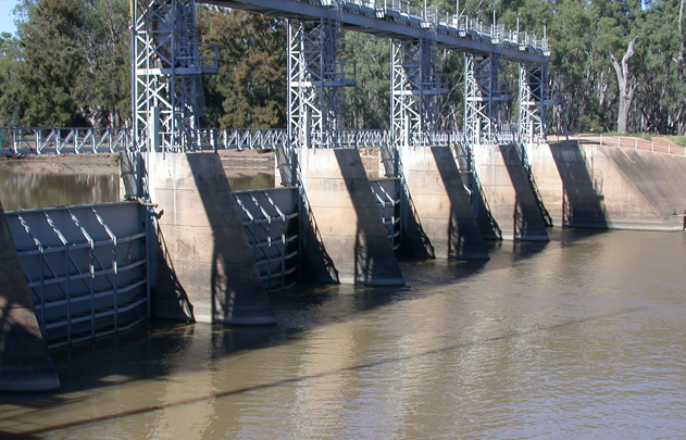
Figure 32. Gogeldrie Weir on the Murrumbidgee River
Theory
Figure 33 shows schematically some of the key features of the weir model to be described. In this example, the weir is built on a river reach as a gated structure that can be lowered to create a vertical wall in the path of the reach, causing some of the water to well up behind the wall, forming a weir pool. When the wall is lowered, it does not reach down to the bed but allows some of the water to flow below the wall, while some of the water also wells up to form a weir pool.
Figure 33. Weir Overview
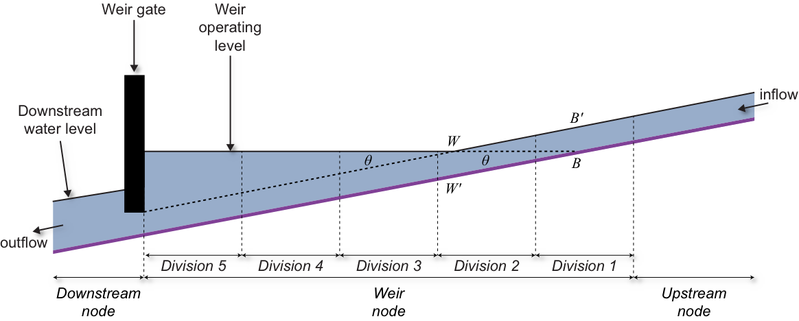
From this it is clear that the weir incorporates both a routing component - the water that continues to flow downstream and can be viewed as a region beneath the main weir - and a non-routing component, above the routing component, which consists of the water that forms the weir pool.
In addition, the reach on which the weir is built is normally treated as composed of a number of divisions (sub-reaches), each of which needs to be processed separately (refer to Figure 33, where the divisions are indicated).
The approach taken in the modelling described here is first to perform calculations based on the assumption that the weir is not present.