Note: This is documentation for version 5.0 of Source. For a different version of Source, select the relevant space by using the Spaces menu in the toolbar above
Fully mixed water quality constituent routing - SRG
Overview
Description and rationale
This SRG page describes the method used in Source for fully mixed routing of conservative water quality constituents (e.g. salt) through a river channel network, including exchanges of constituent fluxes in storages, wetlands, other water features and water infrastructure. The method is appropriate for modelling the transport of most conservative constituents within stream channels, and can be appropriate where the modeller is interested in monthly or annual loads. The method is inherently stable and is not affected by sudden changes in either concentration or flow.
Source can maintain a constituent mass balance at a node with storage and in a link division under cease to flow conditions as the dead storage evaporates, by allowing the modeller to specify a small nominal storage volume to be maintained in each reach division at all times.
Model elements that require this routing functionality include:
- Links (storage routing and lag)
- All node types where
- water can be stored (including wetlands and their wetland hydraulic connectors), or
- water can enter or be lost from the river system, or
- water can be diverted out or released from a channel or storage, or
- tributaries join.
Hence, model elements that require conservative constituent functionality include:
- Link
- Inflow Node
- Splitter Node (Regulated and unregulated)
- Confluence Node
- Minimum Flow Node (used to generate orders for dilution flows)
- Storage Node (These model reservoirs, wetlands and re-regulating weirs. Flows are routed through weirs using the same methodology as links)
- Supply Point Node
- Water User Node and associated demand models
- Environmental Demand Node
- Loss Node
- Gauge Node
- Wetland Hydraulic Connector Node
Scale
Fully mixed, conservative water quality constituent routing operates at the same spatial scale as link routing and operates at every model time-step when it is activated.
Principal developer
eWater CRC.
Scientific Provenance
The technique has been used in various water quality models since the 1970s.
Version
Source version number 3.8.12.
Dependencies
Each link where fully mixed, conservative water quality constituent routing is activated requires a node at its upstream end to define constituent inputs, and a node at the downstream end to process constituent outputs as appropriate. It is also dependent on the translation or routing of flow (inflow, outflow, storage, losses and gains for each division).
For each node where this form of water quality routing is activated, sufficient information about water quantity inputs and outputs, and storage where applicable, is required to enable a constituent mass balance to be calculated at the node.
Structure & processes
Assumptions/Limitations
The following assumptions/limitations apply:
- Constituents are fully mixed in all water bodies being modelled, including storages, wetlands and river channels (e.g. no stratification).
- Constituents can decay but there are no exchanges between constituents.
- Any number of constituents can be modelled.
- Advection and dispersion of constituents is not modelled.
- Processes such as adsorption/desorption and deposition/re-entrainment are not modelled.
- Exchanges with the atmosphere are not modelled (e.g. heat exchange).
- Concentration of all constituents in groundwater is constant (specified by the modeller); this is consistent with the assumption that groundwater storage is infinite.
- Concentration of all constituents in evaporation is always zero.
- Concentration of all constituents in rainfall is also assumed to be zero. However, if it is required to model constituent contribution in rainfall this could be done via a modeller specified function in the AdditionalInflowLoad property.
Theory
The routing methodology is based on the following key principle:
- Mass balance of modelled constituents is maintained in all divisions of all links and at all nodes in the river system being modelled (note that at some node types, such as the Off-Allocation Node, constituents are simply passed through unchanged, at every time step).
Travel times for constituents through lagged routing links are one time step per division. In storage routing links:
- If the flow is moving fast, some or all of the constituents may move through more than one division in a single time step.
- If the flow is not moving fast, some or all of the constituents may remain in a division for more than one time step.
There are no time delays at nodes with no storage.
All calculations for this methodology take place every time step, after the Flow Phase calculations for water are completed for the time step.
Variables
Definitions of variables used are listed in Table 1.
Table 1. Definitions of variables used
Symbol | Purpose/Description | Units |
C(t) | Concentration of a constituent at a model element (node or link) after adjusting for incoming constituent masses and inflows from all sources during the current time step, t. | mg/L |
Cus(t) | Concentration of a constituent entering a model element (node or link) from the mainstream model element immediately upstream during the current time step, t. | mg/L |
Ctrib(t) | Concentration of a constituent entering the river system at an Inflow Node or joining the main stream at a Confluence Node during the current time step, t. | mg/L |
Cgw | Concentration of a constituent in groundwater (i.e. in lateral flow). | mg/L |
Cout(t) | Concentration of a constituent outflowing downstream from a model element at the end of the current time step, t. | mg/L |
D | Small additional storage volume which is not subject to evaporation or other fluxes, to provide a repository for the residual mass of constituent(s) at nodes with storage and in storage routing links under cease to flow conditions. | volume |
Evap(t) | Evaporation at a model element during the current time step, t. If the model element has no surface area this term will be zero. | volume |
M(t) | Mass of a constituent at a node at the end of the current time step, t. | mass |
Mus(t) | Mass of a constituent entering a model element from the mainstream model element immediately upstream during the current time step, t. | mass |
Mtrib(t) | Mass of a constituent entering the river system at an Inflow Node or joining the main stream at a Confluence Node during the current time step, t. | mass |
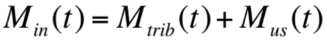
Min(t) | Mass of a constituent entering a model element from immediately upstream during the current time step, t. That is: | mass |
Mgwin(t) | Mass of a constituent entering a model element from groundwater (i.e. with lateral flow) during the current time step, t. | mass |
Mloss(t) | Mass of a constituent lost from the system at a model element due to causes such as seepage, leakage to groundwater and other loss fluxes (excluding evaporation) during the current time step, t. | mass |
Mdivout(t) | Mass of a constituent diverted at a node, such as a Splitter Node or a Supply Point Node, or released from storage into a secondary waterway, during the current time step, t. | mass |
Mout(t) | Mass of a constituent outflowing down the main stream below a model element during the current time step, t. | mass |
Pv(t) | Volume of rainfall on a model element during the current time step, t. If the model element has no surface area this term will be zero. | volume |
t | Index of the current time step | n/a |
V(t-1) | Volume of water in a model element at the end of the previous time step, (t-1). | volume |
Vus(t) | Volume of water entering a model element from the mainstream model element immediately upstream during the current time step, t. | volume |
Vtrib(t) | Volume of water entering the river system at an Inflow Node or joining the main stream at a Confluence Node during the current time step, t. | volume |
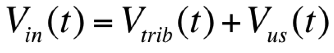
Vin(t) | Volume of water entering a model element from immediately upstream during the current time step, t. That is: | volume |
Vgwin(t) | Volume of water entering a model element from groundwater (i.e. due to lateral flow) during the current time step, t. | volume |
Vloss(t) | Volume of water lost from the system at a model element due to causes such as seepage, leakage to groundwater and other loss fluxes (excluding evaporation) during the current time step, t. | volume |
Vdivout(t) | Volume of water diverted at a node, such as a Splitter Node or a Supply Point Node, or released from storage into a secondary waterway, during the current time step, t. | mass |
Vout(t) | Volume of water outflowing down the main stream below a model element during the current time step, t. | volume |
Mass balance of constituents at nodes
The starting point for the calculation of the mass balance of a given constituent at a node in the current time step is the constituent mass at the node at the start of the current time step (i.e. at the end of the previous time step), M(t-1), noting that M(t-1) and V(t-1) are equal to zero if the node has no storage.
Nodes with no storage and nodes with storage when water is flowing
The overall mass balance equation at a node for a single constituent in the current time step, t, is evaluated in the following steps:
1. The mass at the node at the end of the previous time step is updated for constituent mass entering during the current time step.
| Equation 1 | 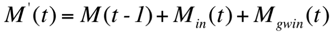 |
|---|
Where:
| Equation 2 |  |
|---|
and
| Equation 3 | 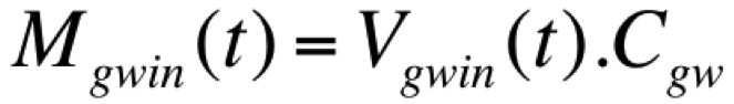 |
|---|
2. With the mass of constituent entering known, and the volume of water entering also known (from Flow Phase calculations), the constituent concentration at the node is updated.
| Equation 4 | 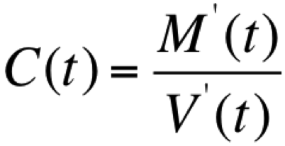 |
|---|
Where:
| Equation 5 |  |
|---|
For nodes with no storage, if the result from Equation 5 is negative then:
V’(t)=0 and C(t)=0 (also see section Nodes with storage and link divisions when water has ceased to flow, below, for more information).
3. Outflowing constituent masses are calculated.
| Equation 6 | 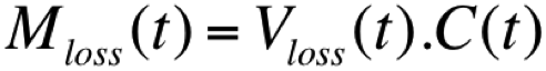 |
|---|
| Equation 7 | 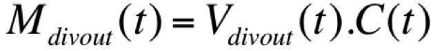 |
|---|
and
| Equation 8 | 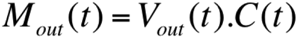 |
|---|
Where the node has no storage, and if there are no losses or diversions, this formulation gives straight translation, with no time delay. It also avoids the problem of numerical diffusion.
Wetland hydraulic connectors
The steps described above apply to wetland hydraulic connectors. However, it should be borne in mind that the direction of flow and of constituent transport can change between time steps.
Nodes with storage and link divisions when water has ceased to flow
In this situation the volume of water in storage continues to be depleted by evaporation, causes such as seepage and leakage to groundwater and, possibly, diversions/releases. The storage volume may be augmented by inflow from groundwater (i.e. lateral inflow). However, circumstances may arise where the remaining volume of water is completely depleted but there is still constituent mass in the storage (this will occur when the storage empties due to evaporation). To avoid potential numerical problems (due to concentrations becoming infinite), Source uses a very small additional storage volume, D, which is not subject to evaporation or other fluxes, to provide a repository for the residual mass of constituent(s). In this case, as the storage available to be depleted becomes small and D starts to become a significant proportion of the total, Equation 4 becomes:
| Equation 9 | 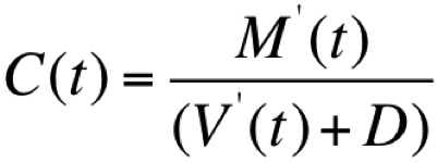 |
|---|
Mass balance of constituents in lagged flow links and no routing links
The calculation of the mass balance of a given constituent in these links follows the same steps as for a node with no storage, described in the Mass balance of constituents at nodes section above. Once the mass balance calculations are completed:
- In the case of a lagged flow link, the outflowing constituent mass is lagged by the average travel time through the link, in the same way as the water. That is, the mass is lagged by one time step per division in the link, where the number of divisions is equal to the number of time steps of lag.
- For a no routing link, the outflow mass is passed without delay, in the same way as for a node without storage.
Mass balance of constituents in storage routing links
The mass balance of constituents in a storage routing link are represented by a cascade of fully mixed storages, one storage for each division.
Overview
If there are lateral inflows and outflows, they are treated the same as inflows and outflows.
The methodology for storage routing of water in links includes partitioning the link into divisions of equal length, as described in the Link storage routing - SRG page. For fully mixed constituent routing, the routing calculations are performed for each division individually.
For each division except the first and last in a link, the outflow and constituent load (i.e. the output) from the division upstream become the input to the next division downstream. The input to the first division is the output from the node immediately upstream and the output from this division becomes the input to the next division downstream. The output from the last division becomes the input to the node immediately downstream.
In storage routing, the lateral fluxes are specified for the routing link as a whole, and these are averaged for each division.
Note that constituent masses are not calculated for losses, outflows to groundwater or other lateral outflow fluxes. Omitting these does not affect any constituent mass balances or constituent concentrations in a division or a link as a whole, or elsewhere (although they are implicitly taken into account via the water balance calculations).
See the section Nodes with storage and link divisions when water has ceased to flow, above, for information on how the mass balance in storage routing links is handled under cease to flow conditions.
Storage Routing Steps
(The following are performed for each constituent)
Setup
1. Lateral Flow Concentration is obtained from associated Catchment Constituent Provider
2. Lateral Flow Mass = Lateral Flow Concentration * Lateral Flow Volume
3. Initial Mass = Stored Mass from previous Time Step (or initial settings on first time-step)
4. Groundwater Concentration is obtained from Constituents Model
5. Groundwater Inflow Mass = Groundwater Concentration * Groundwater Inflow Volume
6. TimeSeries Flux Concentration is obtained from Constituents Model
7. TimeSeries Flux Mass = TimeSeries Flux Concentration * TimeSeries Flux Volume
8. Total Additional Inflow Volume = Lateral Inflow Volume + Timeseries Flux Volume + Groundwater Inflow Volume
9. Additional Inflow Mass is obtained from Constituents Model
10. Total Additional Inflow Concentration = (Additional Inflow Mass + Lateral Inflow Mass + Timeseries Flux Mass + Groundwater Inflow Mass) / Total Additional Inflow Volume
For each time step:
Division processing
1. Division Initial Mass = Division Stored Mass from Previous Time Step
2. Division Upstream Concentration = Previous Division Downstream Flow Concentration (for the First Division, this is the Link’s Upstream Concentration)
3. Division Upstream Mass = Division Upstream Flow Concentration * Division Inflow
4. Division Total Inflow = Division Inflow + ((Lateral Inflow + Timeseries Flux + Groundwater Inflow Flux) / Num Divisions)
5. Division Total Inflow Mass = Division Upstream Mass + ((Link Additional Inflow Mass + Link Lateral Inflow Mass + Link Timeseries Flux Mass + Link Groundwater Inflow Mass) / Num Divisions)
Where:
Link Additional Inflow Mass is obtained from Constituents Model
Link Lateral Flow Mass = Link Lateral Flow Concentration * Link Lateral Flow Volume
6. Division Total Inflow Concentration = Division Total Inflow Mass / Division Total Inflow
7. Calculate outflow mass as follows:
IF (Division Outflow > Division Storage At Start Of Time Step)
THEN
- Division Downstream Flow Mass = (Division Outflow – Division Storage at Start of Time Step) * Division Total Inflow Concentration + Division Initial Mass
ELSE
- Division Downstream Flow Mass = Division Outflow * Division Initial Mass / Division Storage At Start Of Time Step
8. Division Downstream Flow Concentration = Division Downstream Flow Mass/ Division Outflow
9. Division Stored Mass = Division Total Inflow Mass + Division Initial Mass – Division Downstream Flow Mass
Final Division processing
1. Link Downstream Flow Concentration = Final Division Downstream Flow Concentration
2. Link Downstream Flow Mass = Final Division Downstream Flow Mass
3. Link Stored Mass = Sum of All Division Stored Mass
Constituent Processing Models
Constituent processing models alter the mass of constituents in a storage or link. For more information please see the scientific reference guide entry on Constituent Processing Models.
Data
Input data
In addition to the data required for water quantity modelling, the following data is needed for fully mixed constituent routing:
- Time series of constituent concentrations with inflows at Inflow Nodes and with inflows from tributaries at Confluence Nodes where these concentrations are not modelled.
- Constituent concentrations with lateral inflows for all applicable nodes and links (constant in time, but can vary between individual nodes and links).
- Capacities of the additional storages, D, used when modelling nodes with storage and links.
- Initial values of constituent concentrations in nodes with storage and links.
Further details on data requirements are provided in the Source User Guide.
Output data
Outputs include time series of constituent concentrations and loads at locations specified by the modeller.